


This version (09 May 2012 17:14) was approved by Jason Coutermarsh.
Agilent VEE
Connecting to VEE involves the same commands as used in other applications, using the .NET Operation Builder. Follow these steps to create a basic connection to a DPG and download data. For a complete function reference, see the Programming Reference section.
- On the Device menu, select .NET Assembly References… Scroll through the list under Available References and select mscorlib. Click the >> button to add mscorlib to the Selected References list. Click Browse… and browse to the folder where DPGDownloader was installed (typically C:\Program Files (x86)\Analog Devices\DPG\). Select AnalogDevices.DPG.Interfaces.dll.
 Click OK.
 - Select AnalogDevices.DPG.Interfaces and click ». Select System.Collections and click ».
 Click OK.
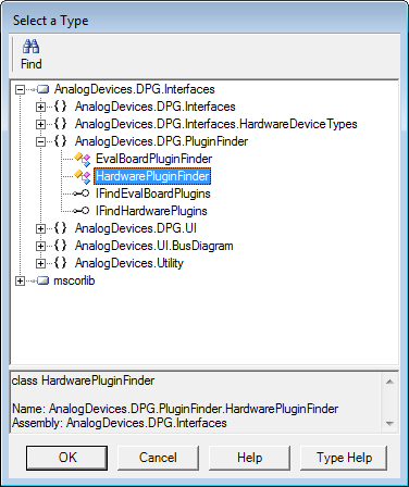
 - Select Device > .NET Operation Builder... Expand AnalogDevices.DPG.Interfaces, then expand AnalogDevices.DPG.PluginFinder and select HardwarePluginFinder.
 Click OK. Place the object in your work area. Double click in the object where it displays < Double-Click to Add Operation >. Select CreateInstance.
  Click OK. Click OK again on the Edit “CreateInstance” screen.
 - Open the .NET Operation Builder again. Select HardwarePluginFinder again, click OK, and double click in the object again. Select FindPlugins from the list, and select OK. Click OK on the Edit “FindPlugins” window. Wire the output of the first object hardwarePluginFinder to the input of the second object hardwarePluginFinder.

- Open the .NET Operation Builder again, this time selecting mscorlib, System, and then Array. Double-click the object where indicated, and select GetValue. Note that there are several GetValues in the list. Select the one that displays System.Object GetValue(Int32 index) in the lower box.
 Click OK in the Edit “GetValue” box, leaving the index set to 0. Connect the return output of the previous object to the array input of the new object.
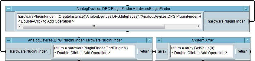
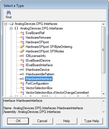
- Open the .NET Operation Builder, selecting AnalogDevices.DPG.Interfaces, AnalogDevices.DPG.Interfaces, IHardwareInterface.
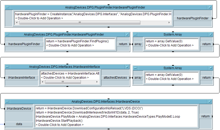
 Double-click the object and select AttachedDevices and click Get. Click OK on the Edit “AttachedDevices” window. Wire the return output of the previous object to the iHardwareInterface input of the new object. Create another System.Array block as in step 5 and connect to the output of the object just created.
- There is now a reference to the first DPG found on the system. From here, the DPG can be configured, loaded with data, and playback started. Open the .NET Operation Builder, selecting AnalogDevices.DPG.Interfaces, AnalogDevices.DPG.Interfaces, and IHardwareDevice. Double-click the new object, and select DownloadConfigurationNoReload and click OK. On the Edit “DownloadConfigurationNoReload” screen, enter in the desired configuration name on the config line. In this example, LVDS (DCO) is used. The correct value will depend on the evaluation board connected to the DPG.
- Double-click the object again and select DownloadInterleaveVectorInt1D and click OK. In the Edit “DownloadInterleavedVectorInt1D” window, enter 2 for channels, and change ShowProgress to True, and click OK. This adds a new input: data. The data input is expecting a 1D array of integers. The data is interleaved between the two ports of the DPG. Some parts, for example a dual DAC with a 16-bit interface, will often require interleaving the two channels of the DAC into a single port of the DPG.
- Double-click the object again and select PlayMode and click Set. In the Edit “PlayMode” window, press OK to select the default of Loop mode.
- Double-click the object again and select StartPlayback and click OK, and then click OK again.
The setup is now complete for loading data into the DPG.
resources/eval/dpg/vee.txt · Last modified: 09 May 2012 17:14 by Jason Coutermarsh