


This version (09 Jan 2021 00:38) was approved by Robin Getz.The Previously approved version (03 Jan 2021 21:56) is available.
Table of Contents
CN0345 Evaluation Board and Software User Guide
Overview
CN0345 is a cost effective low power multichannel data acquisition system that is compatible with standard industrial signal levels. The components are specifically selected to optimize settling time between samples, providing 18-bit performance at channel switching rates up to roughly 750 kHz.
The CN0345 can process eight gain-independent channels and is compatible with both single-ended and differential input signals. The analog front end includes the ADG1207 multiplexer, the AD8251 programmable gain instrumentation amplifier (PGIA), the AD8475 as a precision ADC driver for performing the single-ended-to-differential conversion, and the AD7982, an 18-bit, 1 MSPS PulSAR ADC. Gain configurations of 0.4, 0.8, 1.6, and 3.2 are available.
The maximum sample rate of the system is 1 MSPS. The channel switching logic is synchronous to the ADC conversions, and the maximum channel switching rate is 1 MHz. A single channel can be sampled at up to 1 MSPS with 18-bit resolution. Channel switching rates up to 750 kHz also provide 18-bit performance. The system also features low power consumption, consuming only 240 mW at the maximum ADC throughput rate of 1 MSPS.
This user guide will discuss how to operate the EVAL-SDP-CB1Z and the evaluation software to configure and collect data from the EVAL-CN0345-SDZ Evaluation Board (CN-0345 Board). A complete design support package for the EVAL-CN0345-SDZ evaluation board containing schematics, layouts (native and Gerber), and bill-of-materials can be found at: CN0345-DesignSupport.

Required Equipment
- EVAL-CN0345-SDZ Evaluation Board
- EVAL-SDP-CB1Z Controller Board (SDP-B Board)
- +6V to +12V power supply or wall wart (+9V wall wart included)
- PC with a USB port and Windows® XP, Windows Vista® (32-bit), or Windows 7, 8 or 10 (32-bit) with .NET 4.0 framework installed (included in installation of SDP Drivers)
- USB type A to USB type mini-B cable
- Precision signal generators/dc sources
General Setup
- The EVAL-CN0345-SDZ board connects to the EVAL-SDP-CB1Z SDP-B Board via the 120-pin connector.
- Refer to the Jumper Settings table for setting the EVAL-CN0345-SDZ board to the desired power, reference, and signal chain configuration.
- The included +9V power supply connects to either P19 on EVAL-CN0345-SDZ.
- The EVAL-SDP-CB1Z SDP-B Board connects to the PC via the USB cable.

Installing the Software
- Download the CN0345 Evaluation Software and unzip the CN0345_Evaluation_Software.zip folder and run setup.exe.


- Click Next to view the installation review page.

- Click Next to start the installation.

- Upon completion of the installation of the CN0345 Evaluation Software, click Next for the installer of the ADI SDP Drivers to execute. (The SDP drivers include an installation of the .NET 4.0 framework.)


- Press Next to set the installation location for the SDP Drivers.
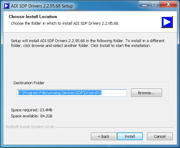
- Press Install to install the SDP Drivers and complete the installation of all software. Click Close when done.


Connecting the Hardware
- Configure the various jumper positions to the desired settings (refer to the Jumper Settings table below)
- Connect P22 of the EVAL-CN0345-SDZ (CN0345 Evaluation Hardware) to CON A of the EVAL-SDP-CB1Z (SDP-B Board).
- Connect the USB Cable to J1 on the EVAL-SDP-CB1Z (SDP-B Board) and leave the other side of the cable unconnected.
- Connect the included 9V supply to P19 on the EVAL-CN0345-SDZ board.
- Connect the USB Cable to the PC.
Jumper Table
| Jumper Ref Des | Position | Function |
|---|---|---|
| P2 | 1 and 2 | Connects on-board reference to reference buffer (ADR434) |
| P7 | closed | Connects negative supply of ADG1207 to the on-board -15V rail |
| P8 | closed | Connects positive supply of ADG1207 to the on-board +15V rail |
| P12 | closed | Connects negative supply of the AD8251 to the on-board -15V rail |
| P13 | closed | Connects positive supply of the AD8251 to the on-board +15V rail |
| P15 | closed | Connects positive supply of the AD8475 to the on-board +5V rail |
| P16 | closed | Connects VDD pin of the AD7982 to the on-board +2.5V rail |
| P17 | closed | Connects the VIO pin of the AD7982 to the on-board +3.3V rail |
| P18 | 1 and 2 | Connects the SDI pin of the AD7982 to the on-board +3.3V rail |
| P24 | closed | Connects negative supply of the AD8475 to AGND |
| P26 | 1 and 2 | Connects enable pin of the ADG1207 to the on-board +5V rail |
Using the Evaluation Software
Software Control and Indicator Descriptions
Front Panel
Configuration Tab

- Sequences
- Selects the number of sequence iterations to be performed for each acquisition.
- Single Capture
- Initiates a set of conversion sequences as defined in the Program Sequencer pop-up. Each set of conversions contains a number of sequences set by Sequences.
- Continuous Capture
- Initiates multiple sets of conversion sequences as defined in the Program Sequencer pop-up. Each set of conversions contains a number of sequences set by Sequences and repeats until Continuous Capture is depressed.
- VREF
- Determines the value of the reference voltage used in calculations and analysis by the software. Affects aspects of the Waveform and Histogram plots (i.e. volt axis values, LSB-to-voltage conversions, etc.). Should be set to the value of the reference voltage used on the EVAL-CN0345-SDZ Evaluation Board (4.096 V by default).
- Sample Rate
- Sets the sample rate of the AD7982 (in kSPS) and the switching rate of the channel/gain sequence defined in the Program Sequencer. Note: the effective sample rate for each channel in the seqeuence (in kSPS) is equal to the value in Sample Rate divided by the number of channels in the sequence.
- SCK
- Selects the frequency of the SCK signal, which determines the rate of sample data readback on the SDO pin of the AD7982. Note: In order to read back all 18 bits of each conversion, the period of the SCK signal must be shorter than the acquisition time divided by 18. The value of Sample Rate therefore determines the minimum SCK rate.
- CHANNEL/GAIN SEQUENCER
- Initiates the Program Sequencer pop-up. See the Program Sequencer section below.
- SET CHANNEL/GAIN MANUALLY
- Initiates the Set Channel/Gain Manually pop-up. See the Manual Set section below.
Multi-Channel Tab

- Multi-Channel Waveform Plot
- Displays the data readback from each of the active and visible channels in the conversion sequence.
- Multi-Channel Selectors
- Selects which channels' data are visible on the Multi-Channel Waveform Plot. Note: channels must be included in the sequence to be displayed.
- Y-Axis Display Format
- Selects whether the data will be displayed in raw code values or in equivalent voltage. Note: code value to voltage conversions are calculated based on the value of VREF in the Configuration Tab.
- X-Axis Display Format
- Selects whether the X-axis will be displayed in sample number/sequence iteration or in time (seconds). Note: when the Samples box is checked, the X coordinates refer to the sample number of each channel, not the aggregate sample number. This is equivalent to the iteration of the conversion sequence. When the Time box is checked, the X coordinates refer to the time at which that particular sequence began relative to the beginning of “sequence 0.” The sample-to-time conversion is calculated based on the number of channels in the conversion sequence and the value in Sample Rate in the Configuration Tab.
- Multi-Channel Waveform Graph Palette
- Sets the display range of the Multi-Channel Waveform Plot.
Single-Channel Tab

- Waveform/Histogram/FFT Sub-tabs
- Selects whether to display the Waveform, Histogram, or FFT data and analysis items for the selected channel.
- Waveform/Histogram/FFT Plot
- Displays the Waveform/Histogram/FFT of the sampled data.
- Single-Channel Selectors
- Selects which channel's Waveform, Histogram, and FFT are being displayed. Note: only one channel can be displayed at once. Channels that are not included in the sequence can be selected, but their plots will not contain any data.
- Y-Axis Display Format
- Selects whether the data will be displayed in raw code values or in equivalent voltage in the Single-Channel Waveform Plot. Note: code value to voltage conversions are calculated based on the value of VREF in the Configuration Tab.
- X-Axis Display Format
- Selects whether the X-axis will be displayed in sample number/sequence iteration or in time (seconds). Note: when the Samples box is checked, the X coordinates refer to the sample number for each channel, not the aggregate sample number. This is equivalent to the iteration of the conversion sequence. When the Time box is checked, the X coordinates refer to the time at which that particular sequence began relative to the beginning of “sequence 0.” The sample-to-time conversion is calculated based on the number of channels in the conversion sequence and the value in Sample Rate in the Configuration Tab.
Pop-up Menus
Program Sequencer

- Select All
- Checks all of the Channel Selectors.
- Deselect All
- Unchecks all of the Channel Selectors.
- Channel Selectors
- Selects which channels are included in the channel/gain sequence.
- Gain Selectors
- Sets the gain for each of the channels included in the channel/gain sequence.
- OK
- Updates the sequence based on the states of the Channel Selectors and Gain Selectors. Closes the Program Sequencer pop-up.
- CANCEL
- Disregards changes made to the sequence and closes the Program Sequencer pop-up.
Set Channel/Gain Manually

- Channel Set
- Selects the channel to be set.
- Gain Set
- Selects the gain to be set.
- SET
- Sets the state of the channel and gain according to the values in Channel Set and Gain Set. Closes the Set Channel/Gain Manually pop-up. Note: take care to ensure the input signal for the channel/gain combination being set is compatible with the system's input range.
- CANCEL
- Closes the Set Channel/Gain Manually pop-up without changing the state of the channel and gain.
Edit Plot Colors

- Plot Color Selectors
- Sets the color for each channel's plot, the plot background, and grid lines.
- Example Display
- Displays an example plot with currently selected colors in Plot Color Selectors.
- UPDATE
- Updates the plot color properties in the Multi-Channel and Single-Channel tabs to those indicated in the Plot Color Selectors. Closes the Edit Plot Colors pop-up.
- DEFAULT
- Resets the Plot Color Selectors to their default values.
- CANCEL
- Disregards changes made to the plot color properties and closes the Edit Plot Colors pop-up.
Runtime Menu Items
File
- Connect to SDP
- Establishes connection between EVAL-SDP-CB1Z (SDP-B Board) and the CN0345 Evaluation Software.
- Program Sequencer
- Opens the Program Sequencer pop-up.
- Set Channel/Gain Manually
- Opens the Set Channel/Gain Manually pop-up.
- Load State
- Selects a previously saved CN0345 Evaluation Software state (see Loading/Saving States).
- Save State
- Saves the current state of the CN0345 Evaluation Software as a .csv file (see Loading/Saving State).
- Exit
- Closes the CN0345 Evaluation Software.
Edit
- Reinitialize to Default
- Reset the CN0345 Evaluation Software to its default state. Note: this involves dumping current conversion results/analysis. Conversion results can be saved by selecting File>Save State (see the Loading/Saving States section below).
- Edit Plot Colors
- Opens the Edit Plot Colors pop-up.
Help
- Analog Devices Website
- User Guide
- Opens the CN0345 User Guide page using the PC's current default web browser.
- Context Help
- Opens the Context Help pop-up. The pop-up gives a brief description of a control when the mouse is hovering above it.
- About
- Displays the current version information of the CN0345 Evaluation Software in a pop-up.
Establishing a USB Connection Link
- Verify that the most recent SDP drivers are properly installed (see Installing the Software).
- Ensure that the CN0345 Evaluation Hardware and the SDP-B Controller Board are correctly connected and powered up (see Connecting the Hardware).
- Run the CN0345 Evaluation Software (CN0345.exe).
- If the CN0345 Evaluation Hardware is properly connected to the PC, the evaluation software will automatically establish a connection with the SDP-B Controller Board. A window with a progress bar will appear.

- If the software does not detect the CN0345 Evaluation Hardware, a pop-up will appear with options to reattempt the connection or to run the software in stand-alone mode (see the Using Stand-Alone Mode section below). Selecting Rescan will attempt to establish the USB connection again. Selecting Cancel will instruct the software to run in stand-alone mode.


Using Stand-Alone Mode
The CN0345 Evaluation Software can run in stand-alone mode when the evaluation hardware is not present. In stand-alone mode, the user can still load states to view previous sets of conversion results (see Loading/Saving States), but cannot initiate new conversions. Stand-alone mode can be terminated by either closing the software or by selecting File>Connect to SDP in the run-time menu.
Stand-alone mode is initiated when the evaluation software fails to establish a connection with the hardware and the user selects Cancel in the pop-up that appears. A pop-up will appear explaining that the CN0345 Evaluation Software will be running in stand-alone mode.

Loading/Saving States
The CN0345 Evaluation Software can store a set of conversion results, a sequence configuration, and plot colors and visibility in a .csv file. These states can be recalled by loading this .csv file, allowing for viewing of old conversion results, etc.
To save a state:
- Press File>Save State.
- Specify a file name. Make sure this file is a .csv file.
To load a state:
- Press File>Load State.
- Select a previously saved state file.
- Ensure that the file being loaded is a CN0345 Evaluation Software state file, or the software may behave unexpectedly.
Configuring a Conversion Sequence
The sequence configuration establishes the order of channel and gain settings in a sample sequence. Sequence configurations are defined using the Program Sequencer pop-up. This can be accessed either by pressing the CHANNEL/GAIN SEQUENCER button or by File>Program Sequencer. To program the sequence:
- Open the Program Sequencer pop-up.
- Check the Channel Selectors for the channels to be included in the sequence. The Select All and Deselect All buttons check and uncheck all Channel Selectors, respectively.
- Select the Gain Selectors values to set the gain for each of the active channels in the sequence.
- Press OK to accept the sequence configuration or CANCEL to close the Program Sequencer without changing the sequence.

Capturing Samples
After the sequence is configured and the CN0345 Evaluation Hardware and Software are connected, the software can initiate conversions. To capture samples:
- Set the number of sequences to be performed in each collection of samples using the Sequences control.
- Ensure that the value in VREF matches the reference voltage being used on the CN0345 Evaluation Hardware.
- Select the desired Sample Rate and SCK rate.
- Note that the Sample Rate is the sample rate of the AD7982, not the effective sample rate for each channel.
- Press either Single Capture to perform a single burst of sampling sequences or Continuous Capture to perform repeated bursts of sampling sequences until stopped.
Viewing Conversion Results
After capturing samples or loading a previous set of conversion results, the data and analysis items for each channel can be viewed using the Multi-Channel tab and the Single-Channel tab and its sub-tabs (Waveform, Histogram, and FFT).
- Select the Multi-Channel tab to view every channel's data on a single plot. The Multi-Channel Selectors set the visibility of each channel's data.

- Select the Single-Channel tab to view each channel's data or analysis results independently. The Waveform sub-tab shows the conversion results for that channel. The Histogram and FFT sub-tabs show the dc and ac analysis for each channel's data.


resources/eval/user-guides/circuits-from-the-lab/cn0345.txt · Last modified: 09 Jan 2021 00:32 by Robin Getz