


This version (19 Jun 2017 17:58) was approved by Robin Getz.The Previously approved version (02 Jun 2017 16:11) is available.
Table of Contents
Testing the ADALM-PLUTO
It's one thing to test FMC cards by hand (manually plugging them into a carrier), like the FMCOMMS3, but it is something else to program a high volume board like the Pluto SDR. Not only does the board need to be tested (performance metrics), but the flash needs to be programmed with the most recent files.
Doing this one board at a time is possible with a JTAG and USB cables, invoking Xilinx tools, and device firmware upgrade by hand, and clicking in all the right places, but this would extend test time to ~ 5 minutes a board. Simply testing 1000 boards would take 3.5 days, not including the time it takes to assembly the boards in the cases, and screwing on the locking nuts.
Before automation begins on anything, it's good to look at the cost/reward. On a low volume system, it can take as much time as you want to spend testing something, and it doesn't matter. Examining the excellent chart put together by xkcd, we can see that spending time on automation can be worth it since we are repeating the task many times.

Since we are trying to test ~500 a day, we need the test time to be under 1 minute per board. We would like the folks in the manufacturing factory only to be working on test a few days a month, so we can afford to spend some time on automation.
In order to do achieve our sub one minute test time, we attacked things from two angles; automation, and parallel test. This resulted in an automated quad site tester. This programs, and tests, and calibrates four boards at one time, to reduce operator time and interaction with the boards.

4 PCBs are placed into the unit, and 4 programmed, and calibrated devices come out.

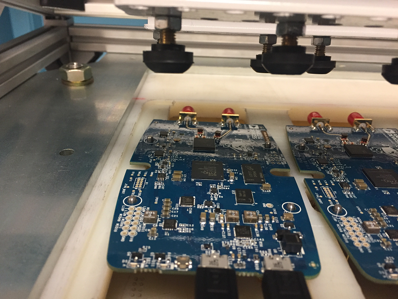
A closer look at things, shows how things work. When boards are placed into the tester, they are aligned via metal posts where the screw holes are. This ensures they are inserted into the correct position in the tester. A “lid” closed, and feet attached to the lid hold the PCBs in place. Finally pogo pins are lifted up from the bottom, and make contact on the bottom of the PCB for things like JTAG, serial console, power supplies, and a few GPIOs for test purposes.


A Raspberry Pi 3 underneath the test harness controls the programming and test process, as well as the LEDS on the front panel to indicate to the tester if boards are good (green LED) or bad (red LED). This also prints out the sticker that is placed on the back of the box with the serial number and MAC addresses.

The large blue button is the shutdown button for all the boards. At the end of the day, simply press (and hold) the blue button will properly shutdown all Raspberry Pi 3 boards, and then simply unplug the test jig.
A signal generator beside the test jig must be programmed to 3.5 GHz (3,500,000,000 Hz) at +20dBm, which the Pluto uses to calibrate the on-board oscillator, as well as test the receiver path.
Test process
- get the jig ready for the first batch:
- plug in all 4 USB LabelWriter® 450 Turbo, into the USB A, B, C and D connectors on the side of the unit.
- plug in the network, to the internet.
- plug in the Analog Devices HMC-T2220, and set it to 3.5 GHz, +20dBm.
- power on the test jig
- the bottom yellow LEDs will start blinking when the system is ready for testing
- lift the handle up to the top. This will lower the pogo pins.
- unlatch the lid for the test jig
- lift the lid
then the tests can start on some boards
- insert 4 PCBs into the test jig.
- plug all four boards into 8 USB cables.
- lower the lid, and latch it.
- pull the handle towards front, to lift the pogo pins up against the PCBs
- press the small blue buttons on the front panel to start testing
- this will light up the first yellow LED, solid (not blinking), this indicates that the test has started.
- The test takes between 2:45 and 3 minutes.
- Once the programming / testing / calibration is complete, either:
- the GREEN LED will light (indicating pass)
- in the pass case, a sticker with the boards serial number will print out. The sticker is specific for a board, and will have a small “A”, “B”, “C”, or “D” on it, to make it easier for the operator to match stickers with boards.
- the RED LED will light (indicating fail)
- once all four sites are complete (either a red or green light), all the PCBs will be powered down, and be ready to either be put in the scrap pile or assembled into the plastic case.
- lift the handle, lowering the pogo pins
- unlatch and lift the top
- remove the boards
- unplug them from USB
- at this time, 4 new boards can be inserted, and the test repeated (start at step one in this list).
- When you are done testing for the day, press the large blue button on the side - that will do a proper system shutdown; then you can unplug the units (when the LEDs have stopped blinking).
Based on this, it should take less than 4 minutes to insert, program, test, calibrate, and remove 4 boards, thus achieving the less than 1 minute per board goal. Then it is a matter of:
- inserting the boards into the case, and making sure to include the top of the case (where the SMAs stick out)
- screwing the 4 screws which hold the PCB into the case
- putting the top on, and screwing the 2 case screws in
- putting the top sticker on
- putting the bottom sticker on
- putting it in the box with the remaining top level BOM (antenna, USB cables, SMA cable, etc).
and then ship it!
details
The details of what is happening is pretty simple.
- openocd loads a minimal u-boot over jtag.
- The running u-boot is probes the serial flash, and enables direct flash update.
- on the Pi, dfu-utils are used program the flash with the two files:
- FSBL, U-Boot
- the Linux kernel, userspace and the bitfile (FPGA)
- the Pi uses Kermit to communicate with U-Boot, and ensure the U-Boot environment is set up
- the power is cycled to ensure the flashed kernel can boot
- the Pluto is checked
- the Pluto is calibrated; the oscillator offset (default +/-25 ppm), to a known frequency to improve performance.
- The u-boot sectors in flash are locked
- the label is printed via glabels
- all this is accomplished via a few expect, python and shell scripts
Video
Since a picture is worth 1000 words, … :)
university/tools/pluto/engineers/testing.txt · Last modified: 19 Jun 2017 17:58 by Robin Getz