By forwarding the trigger signal on one module’s TriggerOut(TO) pin, and reading it on another’s TriggerIn(TI) pin, one can obtain more synchronised channels of both analog and digital inputs. This can be achieved either with Scopy, as well as with libm2k. The following example will provide a description on how to make use of two ADALM2000 modules’ trigger features to have their analog and digital inputs synchronised.
Both modules will read a test signal on their channel 1, respectively the trigger on channel 2. The trigger will be generated using DIO0 of the first ADALM2000. This is going to be transmitted to the second module by connecting its TriggerIn pin to the first’s TriggerOut Pin. You will have to make the connections shown in the diagram below. The connection between the TO and TI pins, highlighted with red, links the two devices' triggers, thus enabling them to acquire data in a synchronised manner.
Here, the trigger is also going to be generated on the first ADALM2000’s DIO0 pin and then forwarding it to the second’s trigger in. Both of the modules’ DIO1 pins will read the same generated waveform. To do this, connect the modules as shown below. Again, the connection which enables the two modules to acquire data simultaneously is the one between the TO and TI pins, highlighted with red.
In order to achieve this with Scopy, you’ll need to open a second instance of Scopy.
MacOS users: To be able to open multiple instances of Scopy, open a terminal widow and run the following command:
open -n /path/to/application/Scopy.app
Open Scopy and connect the first module. Click the button for the Digital I/O instrument and set DIO 0 to output.
Then go to the Oscilloscope and open the Trigger settings menu. Set the trigger mode to normal, channel 2 as source and the condition to Rising Edge.
Then configure the TriggerOut pin to forward the oscilloscope trigger. Click the single button when you’re done and you’ll see that the device is waiting for the trigger signal.
Let’s configure the second module now. Open the second instance of Scopy and go to the Oscilloscope instrument. Open the Trigger Settings menu and set the trigger mode to normal. Then disable the internal trigger and enable the digital one. Set the source to External Trigger In and the condition to rising edge. Once again, click the single button when you’re done.
Go back to the first instance of Scopy. Open the Signal Generator and generate a square waveform of 5 MHz on channel 1. Then, open the Digital I/O instrument and run it. Then set the state of DIO 0 to 1.
You’ll notice that both Oscilloscope instruments were triggered. In the image below, the superior half shows the analog inputs of the module whose trigger signal is being forwarded, while the inferior depicts the second ADALM2000. With the cursors enabled, a delay of approximately 190 nanoseconds is measured.
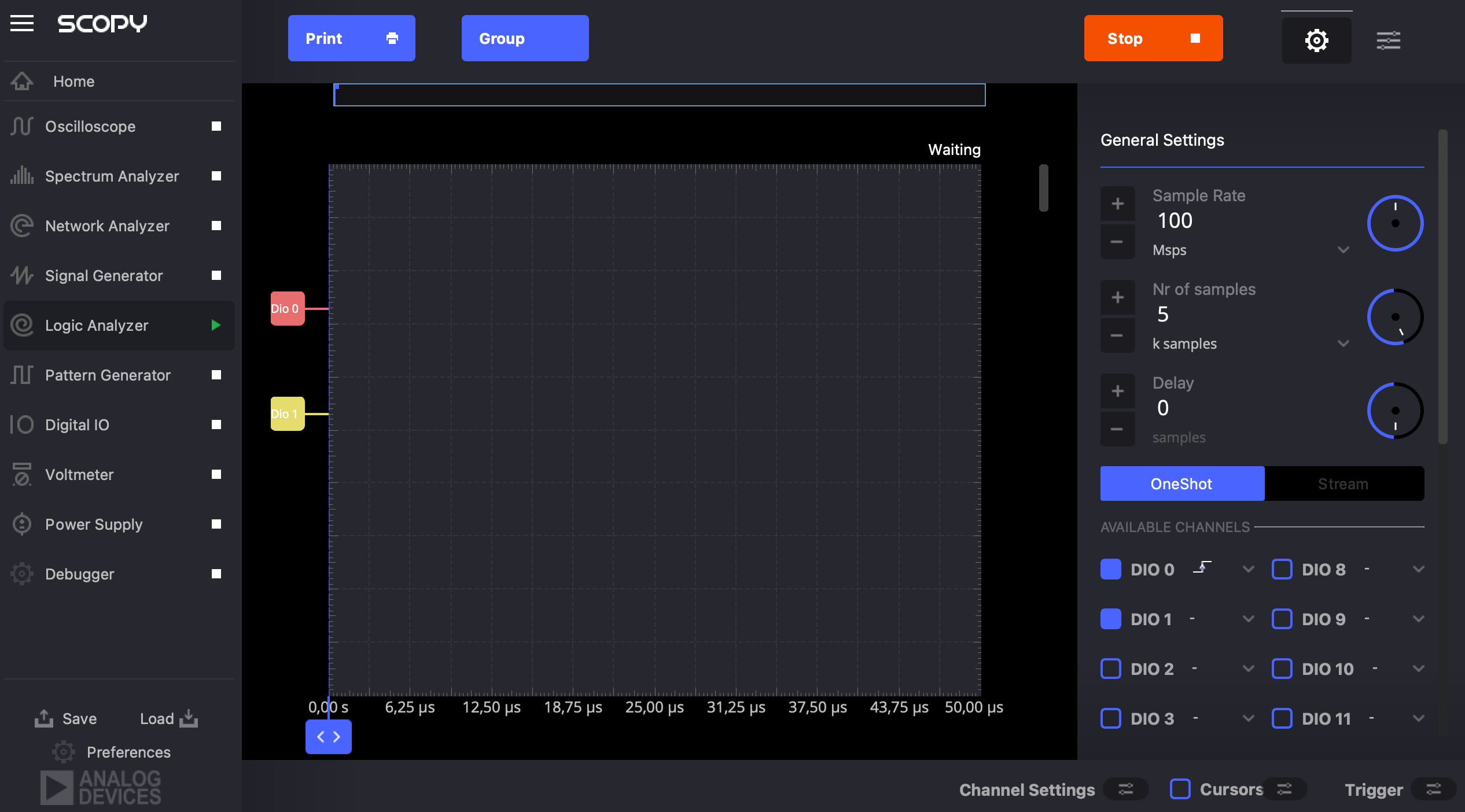
In the Digital I/O Instrument of the first instance of Scopy, keep the DIO0 pin as output and make sure its state is set to 0. Open the Logic Analyser instrument and enable pins: DIO0, DIO1. Set the trigger condition on DIO0 to rising edge.

Then, go to the Oscilloscope’s Trigger settings menu. Here, select the Logic Analyser option for the External TriggerOut configuration.
In the second instance of Scopy, open the Logic Analyser instrument, and enable pins: DIO0 and DIO1. Go to the Trigger menu and set the mode to normal, the source to External Trigger In and the condition to rising edge.
Go to the Patter Generator of the first instance of Scopy and enable DIO7. Generate a clock signal of 5MHz on this pin. Go back to the Digital I/O instrument where we configured our trigger pin. Run the instrument and set the state of DIO0 to 1. Again, you’ll notice that both instruments have triggered. The figure below shows the instance of Scopy from where the trigger is being forwarded in the superior half, while under it the second one is displayed.


If you’ll zoom in on the plot and enable the cursors in the second instance of Scopy, you’ll be able to measure the delay, as shown below.
Maintaining the connections made when demonstrating the synchronisation of the analog inputs using Scopy, the same result can be achieved using the example Python libm2k script. The script follows the exact steps shown in the Scopy section of this tutorial.
As mentioned in the previous sub-section, keep the connections you made when you did this with Scopy and use the Python libm2k script provided with the library. This script also reproduces the steps shown in the Scopy section of this tutorial.
This section offers instructions on how to add more modules to the chain of M2Ks. For example, you can forward the trigger from the second module to a third in the same manner: connect the second M2K’s TriggerOut pin to the third’s TriggerIn pin. If you want to use Scopy, you’ll need to open as many instances as the number of modules you want to use. On the other hand, if you want to use libm2k, you’ll also need to edit the example scripts, to comply with your desired configuration.