| Description | Test Steps | Steps Resources | Expected Results |
| Checking individual digital pin state | 1. Set DIO 0-7 and DIO 8-15 as individual pins | 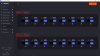 | The interface should look like in the “Step Resources” picture (left side). |
| 2. Set channel 0 as output | 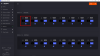 | The interface should look like in the “Step Resources” picture (left side). |
| 3. Set channel 7 as input |  | The interface should look like in the “Step Resources” picture (left side). |
| 4. Connect digital channel 0 to channel 7 via wires. |  | |
| 5. Change the logic state of channel 0 (0/1) multiple times and monitor channel 7 state. | 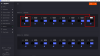  | When channel 0 is set to logic one, channel 7 will be automatically set to logic 1. When channel 0 is set to logic one, channel 7 will be automatically set to logic 1. |
| 6. Connect the channel 0 to voltmeter and channel 7 to the positive power supply. |  | |
| 7. Set channel 0 to logic state 0. |  | The interface should look like in the “Step Resources” picture (left side). |
| 8. Monitor the voltage value via voltmeter. | 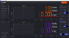 | On the voltmeter the voltage displayed is be between -0.050V and 0.4V. |
| 9. Set channel 0 to logic state 1. | 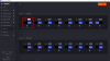 | The interface should look like in the “Step Resources” picture (left side). |
| 10. Monitor the voltage value via voltmeter. |  | On the voltmeter the voltage displayed should be between 2.9V and 3.4V. |
| 11. Set positive power supply to voltage level between 0V and 0.8V. | 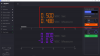 | The interface should look like in the “Step Resources” picture (left side). |
| 12. Monitor the channel 7 logic state. | 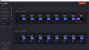 | Channel 7 indicates logic 0 level. |
| 13. Set positive power supply to voltage level between 2V and 3.3V | 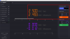 | The interface should look like in the “Step Resources” picture (left side). |
| 14. Monitor the channel 7 logic state. |  | Channel 7 indicates logic 1 level. |
| 15. In step 2 replace by turn channel 0 with channels from 1 to 6 and from 8 to 15. Then, for each replacement repeat steps from 3 to 13. | | |
| 16. In step 2 replace with channel 7 and in step 3 by turn channels from 0 to 6 and from 8 to 15. Then, for each replacement repeat steps from 4 to 13. | | |


