


This version (05 May 2021 13:56) was approved by Joshua Berlin.The Previously approved version (10 Feb 2021 14:30) is available.
Table of Contents
Interfacing SigmaDSP Processors with a Microcontroller
Overview
This guide describes how to integrate a SigmaDSP processor into microcontroller-based systems.
Microcontrollers are available in a wide variety of architectures and capabilities, so rather than creating a fully-featured SigmaDSP library for every processor, we focus here on the principles behind successful SigmaDSP integration so that users can complete designs quickly and efficiently.
Arduino-compatible example code, attached below includes a simple program to boot ADAU1701, ADAU1761, or ADAU1467 processors without any modification. It is written for the Teensy 4.0, so pin assignments should be adjusted for use on other platforms. Teensy 4.0 was chosen because it is easy to use and has enough memory to store even the largest SigmaDSP program. Version 1.1.0 of the code is also tested and working on ESP8266 (with minor changes described below).
This guide takes advantage of C++ header files generated by SigmaStudio which reduce complexity in users' code.
Example Code Version 1.1.0: teensy_sigmadsp_example_project_1.1.0.zip
Notes about Example Code Version 1.1.0
- In line 77 of main.cpp, the reference to SIGMASTUDIOFW.cpp should be SigmaStudioFW.h.
- Line 250 of SigmaStudioFW.h is
byte register_value[dataLength] = {};. For ESP8266 compatibility, it should bebyte register_value[dataLength];. This fix will be in the next release.
Example Code Version 1.0.0: teensy_sigmadsp_example_project_1.0.0.zip
Communications- I2C and SPI
All current SigmaDSP processors are equipped with I2C and SPI control ports. Connecting your microcontroller to one of the control ports allows you to download a SigmaDSP program, read/write registers, and update program parameters on the fly.
SPI is the fastest protocol for communicating between a microcontroller and SigmaDSP processor. Depending on your chosen SigmaDSP the SPI SCLK frequency can be set as high as 20 MHz. It requires four pins on your microcontroller, preferably a hardware SPI port; software SPI implementations are possible but will typically incur high overhead on a microcontroller.
I2C is a slower protocol. Most SigmaDSP processors support a maximum SCL frequency of 400 kHz, although ADAU146x processors are specified up to 1 MHz. I2C requires two pins on your microcontroller, preferably a hardware I2C port; software I2C implementations also incur some microcontroller overhead.
There are many other reasons why either I2C or SPI might be more suitable in your device. For simplicity we won't go into those reasons here. If you are not sure which to use, go ahead and post a question in the EngineerZone support forum. If you describe your application we can guide you through your choice.
In the example code you can switch between I2C and SPI code by toggling #define USE_SPI in USER_SETTINGS.h. To save memory, code for the unused interface will be excluded by the compiler.
Hardware Connections
Logic levels on your microcontoller must be the same as the IOVDD supply of your SigmaDSP, or level shifters should be used. The Arduino Uno uses 5V logic by default which is not directly compatible with SigmaDSP processors.
It is recommended to connect your microcontroller to a working SigmaDSP evaluation board before attempting to program a custom board and verify working communications between the microcontroller and DSP. This allows you to separate the firmware debug process from the hardware debug process.
USBi Connector
All SigmaDSP evaluation boards are outfitted with a 10-pin connector for programming. The connector mates with a USBi programmer (included with all evaluation boards) using the pinout shown here. The USBi connector is also the best way to connect a microcontroller to your evaluation board.
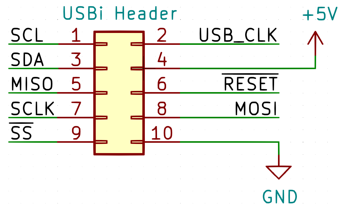
USB_CLK is not a required signal for SigmaDSP development boards, so it is usually left as an open circuit.
Please reference the schematics for your evaluation board's User Guide, which can be found on its product webpage, to determine which interfaces are exposed on connectors. Also note whether your evaluation board includes pull-up resistors on the SCL, SDA, and /SS pins; if they are not present, you must add them.
ADAU1701
The EVAL-ADAU1701MINIZ schematic shows that only I2C is available on the programming header (pins 1 and 3). Additionally, there are no I2C pull-up resistors shown in the schematic so they must be provided by your own hardware. The header also includes a reset pin (pin 6) and 5V power pin (pin 4). In the example code ADAU1701 is referred to as a “Sigma100” processor.
The evaluation board uses 3.3V logic levels. Level shifters are recommended for interfacing with 1.8V or 5V microcontrollers.
The 5V power pin (Pin 4) can be connected to your microcontroller's VUSB pin if sufficient current is available. Be careful not to exceed 500mA total current draw from a USB port.

ADAU1761
The ADAU1761 (referred to as Sigma200) has a similar pinout to the ADAU1701, although I2C pullup resistors are already in place on the board. The evaluation board schematic is available here.
EVAL-ADAU1761Z also allows Pin 4 of the USBi connector to power the DSP. Again, ensure that your system consumes <500mA from a USB port.

ADAU145x/ADAU146x
ADAU145x and ADAU146x processors (also referred to as Sigma300 and Sigma350, respectively) expose communications pins as SPI. Since these processors multiplex SPI and I2C interfaces the header can also program the board over I2C (See the “Example Schematic” section for more information).
Note that Pin 4 of the USBi connector illuminates an LED but does not supply power to the entire board. ADAU145x and ADAU146x processors should be powered through the barrel jack.

Example Schematic
The following schematic based on the Teensy 4.0 microcontroller allows programming of SigmaDSP processors through the USBi programming header and was used for development of the example code. Please click the image to see a full-resolution version.

The 100ohm series resistors are intended to protect the Teensy from short-circuited pins, and the computer's USB port from a short circuit on VUSB. However, if you are powering the evaluation board from the Teensy, R1 must be removed and shorted and care must be taken not to pull more than 500mA from the computer's USB port at any time.
Notice that the SCL and SDA connections are duplicated on the header:
- MISO,SDA appears on both Pin 3 and Pin 5 of the connector.
- SCLK,SCL appears on both Pin 1 and Pin 7 of the connector.
This is because some SigmaDSP development boards connect the I2C interface to the USBi (e.g., ADAU1701), where others connect the SPI interface (e.g., ADAU1466). Connecting I2C to Pin 1 and Pin 3 allows programming of the former; and, including both SPI and I2C connections allows either protocol to be used for the latter.
The same is true for the microcontroller:
- MISO,SDA appears on both Pin 12 and Pin 18 of the Teensy.
- SCLK,SCL appears on both Pin 13 and Pin 19 of the Teensy.
This configuration connects the SPI and I2C interfaces of the Teensy to each other. If the unused interface is turned off (tristated) in software, this allows the Teensy to choose which communications protocol to use without changing hardware. This functionality is included in the example program.
The example code's setup() function drives ADDR0 and ADDR1 to ground if USE_SPI is set to false in USER_SETTINGS.h, placing a Sigma300/Sigma350 DSP at 7-bit I2C address 0b0111000.
Considerations for Self Boot
Microcontroller memory is often in short supply. By configuring the SigmaDSP processor to self boot from an external EEPROM, most of the SigmaDSP program can be excluded from your microcontroller code. However, there are some considerations and common pitfalls to take into account before making this decision:
- Some SigmaDSP processors have only one I2C port which is used for both control and self boot, such as the ADAU1701. I2C is designed for single-master operation, but during self boot the DSP and microcontroller could theoretically attempt to assert control of the bus at the same time, corrupting data.
- One workaround involves disabling Self Boot on the SigmaDSP and programming the microcontroller to transfer the EEPROM contents to the DSP. This way the microcontroller is the only I2C master on the bus.
- The microcontroller should not attempt to use the slave control port while the DSP is performing the self boot operation.
- You can use a one of the SigmaDSP GPIO pins to signal to the microcontroller that programming is complete and it is safe to start using the control port.
Navigating the Example Code
Overview of Included Files
The example code is separated into the following files:
main.cpp: The main program body, which initializes hardware libraries and contains user flowUSER_SETTINGS.h: User-editable configuration variables; use this function to change such things as DSP type, communications protocol, and SPI/I2C transfer speedSigmaStudioFW.h: User-editable functions to communicate with the DSP. This file is required by SigmaStudio export files.
The example code requires some files exported by SigmaStudio which describe the contents of the SigmaStudio project, including register values and parameter locations.
These files are overwritten each time the “Export System Files” button is pressed in SigmaStudio, so be careful to note any changes in another location.
Most applications do not require these files to be altered.
your_project_name_IC_1.h: Contains default control register addresses and values, as well the default_download() function used to program the DSP. The default_download() function executes the exact same flow as “Link-Compile-Download” in SigmaStudio.your_project_name_IC_1_PARAM.h: Contains useful information about algorithm parameters.- Default values
- Addresses in RAM
- Which memory page the parameter is on (for ADAU146x)
your_project_name_IC_1_REG.h: Contains similar information to the _PARAM.h file above, but for control registers instead of algorithm parameters.
SigmaStudio also exports the following files which are not used by the example code.
your_project_name.params: A human-readable description of each parameter in the SigmaStudio project.your_project_name.hex: Contains contents of the program RAM.your_project_name.xml: Another version of the default project parameters in XML format.
Example Code Change Log
1.1.0
- Changed
PRINT_DSP_REGISTERfunction name toSIGMA_PRINT_REGISTERfor consistency - Changed
SIGMA_READ_REGISTERfunction name toSIGMA_READ_REGISTER_BYTESfor consistency SIGMA_PRINT_REGISTERcallsSIGMA_READ_REGISTER_BYTESinstead of double-implementing the commsSIGMASTUDIOTYPE_8_24_CONVERTis now an alias forSIGMASTUDIOTYPE_FIXPOINT_CONVERTSIGMASTUDIOTYPE_FIXPOINT_CONVERTswitches to the proper implementation based on DSP type (8.24 or 5.23 number formats)SIGMASTUDIOTYPE_INTEGER_CONVERTis now a passthrough macrogetMemoryDepthis now under a compiler switch to remove from memory unless I2C is enabled- Added new function call for
SIGMA_WRITE_REGISTER_BLOCKwhich omits the DSP address - Added function
SIGMASTUDIOTYPE_REGISTER_CONVERT - Added function
SIGMA_WRITE_REGISTER_FLOAT - Added function
SIGMA_WRITE_REGISTER_INTEGER - Added function
SIGMA_READ_REGISTER_FLOAT - Added function
SIGMA_READ_REGISTER_INTEGER
1.0.0
Initial Release
resources/tools-software/sigmastudio/tutorials/microcontroller.txt · Last modified: 05 May 2021 13:56 by Joshua Berlin