Click here to return to the Basic DSP page
| Name | Format [int/dec] - [control/audio] | Function Description |
|---|---|---|
| Pin 0: Input | any - any | The input signal to compare to 0 |
| Name | Format [int/dec] - [control/audio] | Function Description |
|---|---|---|
| Pin 0: Output | int - control | The output signal of 0 or 1 in the designated bit position |
| GUI Control Name | Default Value | Range | Function Description |
|---|---|---|---|
| Output Bit Designation | 28 | [28.0 Bit26] | Sets bit position of the output “1” flag. 28.0 is the default values which represents 1LSB. |
| GUI Control Name | Compiler Name | Function Description |
|---|---|---|
| Output Bit Designation | BufferAlg1output1 | Actual value written to DSP from the representation of the drop-down menu to select the bit position of the output “1” flag. |
The following table shows what the data output value will be for given input values, based on the selection from the Drop Down Display.
| Input Pin Value | Drop Down Display | Output Pin Value |
|---|---|---|
| 0 | Any Selection | 0x00 0x00 0x00 0x00 |
| Any non-zero Value | 28 | 0x00 0x00 0x00 0x01 |
| Any non-zero Value | Bit: 1 | 0x00 0x00 0x00 0x02 |
| Any non-zero Value | Bit: 2 | 0x00 0x00 0x00 0x04 |
| Any non-zero Value | Bit: 3 | 0x00 0x00 0x00 0x08 |
| … | … | … |
| Any non-zero Value | 5.23 | 0x00 0x80 0x00 0x00 |
| Any non-zero Value | Bit: 24 | 0x01 0x00 0x00 0x00 |
| Any non-zero Value | Bit: 25 | 0x02 0x00 0x00 0x00 |
| Any non-zero Value | Bit: 26 | 0x04 0x00 0x00 0x00 |
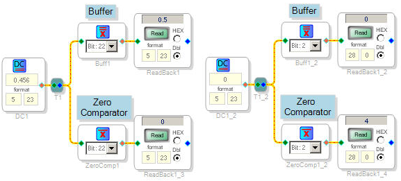
The following schematic image shows both the Buffer and the Zero Comparator for a non-zero and zero input. There results of the algorithm are captured in the DSP Readback cell.

| Toolbox Path | Basic DSP - Logic - Invert - Buffer |
| Cores Supported | ADAU144x ADAU176x ADAU178x ADAU170x AD1940 |
| “Grow Algorithm” Supported | yes - see Algorithm Growth Information |
| “Add Algorithm” Supported | yes - see Algorithm Addition Information |
| Subroutine/Loop Based | no |
| Program RAM | 4* |
| Data RAM | 1* |
| Parameter RAM | 1* |