


This version is outdated by a newer approved version. This version (24 Jun 2020 17:48) was approved by Chad Wentworth.The Previously approved version (19 May 2020 22:35) is available.
This version (24 Jun 2020 17:48) was approved by Chad Wentworth.The Previously approved version (19 May 2020 22:35) is available.This is an old revision of the document!
Table of Contents
SHARC Audio Module(Revision 1.5)
SHARC Audio Module revision 1.4 hardware reference information can be found at Main Board(Revision 1.4)
The SHARC Audio Module uses the ADSP-SC589 SHARC processor along with an ADAU1761 SigmaDSP audio codec and an AD2428W A2B transceiver in a compact form for audio development.
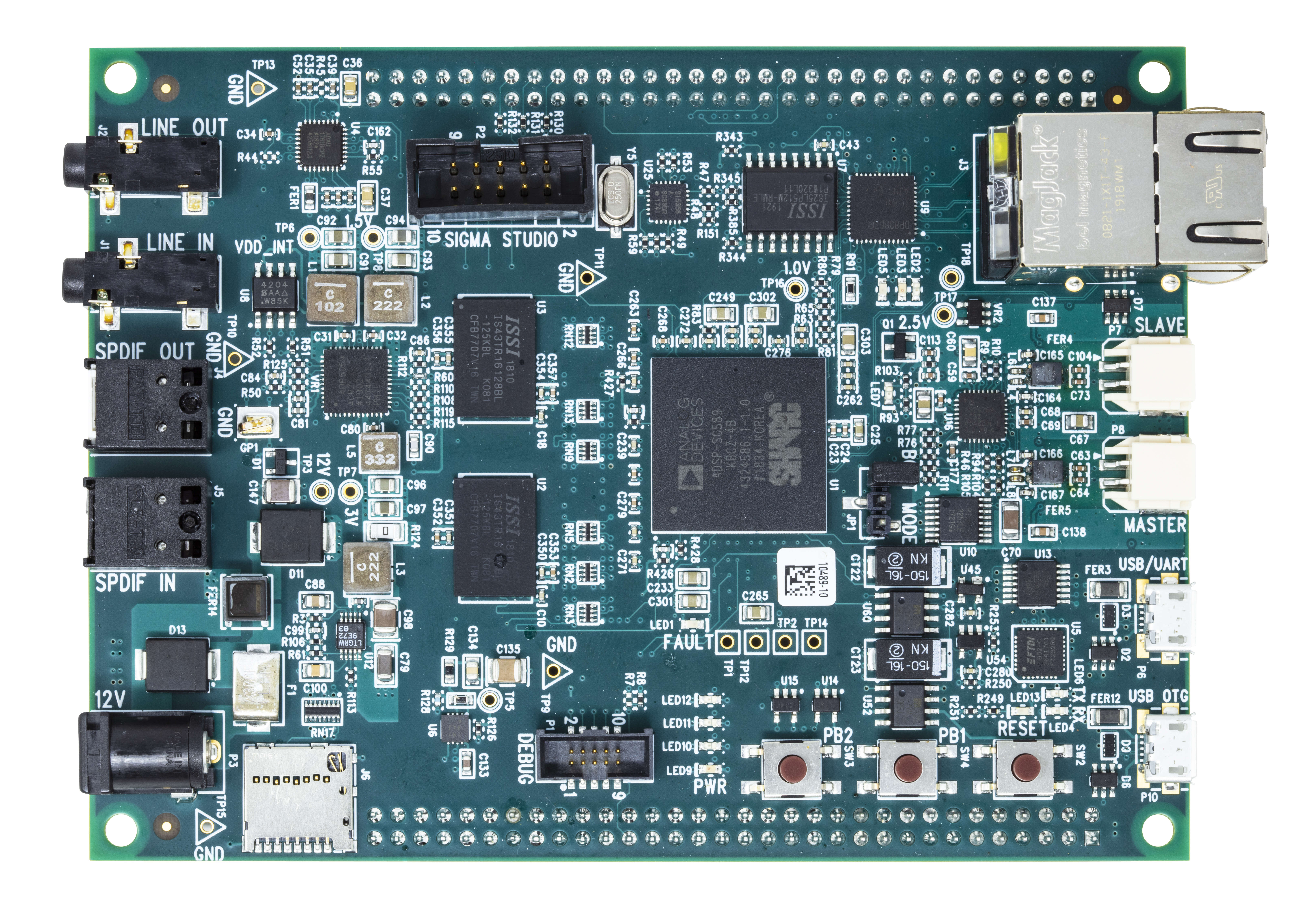
The SHARC Audio Module Main Board

Block Diagram of the SHARC Audio Module Main Board
Main Differences Between Rev 1.5 and Rev 1.4
- SPI flash and DDR memory changed to drop in replacements from ISSI
- FTDI header was replaced with an FTDI chip on board along with a USB connector so no need for a separate FTDI cable
- UART boot was fixed
- USB and Ethernet jacks are now combined into one jack
Schematics, PCB Layout, Bill of Materials
SHARC Audio Module Main Board Rev 1.5 Design and Integration Files
ADSP-SC589 SHARC DSP
The SHARC Audio Module is powered by the Analog Devices, Inc. ADSP-SC589 SHARC DSP. The ADSP-SC589 contains an ARM Cortex-A5 and Dual SHARC+ cores running at 450 MHz.
DDR3 2x 2Gb
There are two DDR3 channels on the SHARC Audio Module, each with a 2Gbit DDR3 module. In the default SHARC Audio Module configuration, one DDR3 module is used for Linux and the other used by the SHARC+ cores for audio processing.
512Mb SPI Flash
A 512Mbit SPI Flash on the SHARC Audio Module that is ready to be programmed with a users desired audio application.
10/100/1000 Ethernet
The SHARC Audio Module has a 10/100/1000 Ethernet module to provide network and internet access to the board.
USB Type A Host Port and USB MicroAB Host/Device/OTG Port
The USB Type A port is Host mode only, and is for USB WiFi, Bluetooth and USB memory devices. The connector is combined with the Ethernet jack.
The USB MicroAB can be a Host/Device or OTG connection. This interface can be used for USB Audio, along with the USBi Emulator.
Expansion Port P4
| +12v | 1 | 2 | +12v |
| GND | 3 | 4 | GND |
| TWI1_SCL | 5 | 6 | PB_00 |
| TWI1_SDA | 7 | 8 | PB_01 |
| GND | 9 | 10 | PB_02 |
| DAI0_PIN13 | 11 | 12 | PB_03 |
| DAI0_PIN14 | 13 | 14 | GND |
| DAI0_PIN15 | 15 | 16 | PB_04 |
| GND | 17 | 18 | PB_05 |
| DAI0_PIN16 | 19 | 20 | PD_14 |
| DAI0_PIN17 | 21 | 22 | PD_15 |
| DAI0_PIN18 | 23 | 24 | GND |
| +3.3v | 25 | 26 | PE_00 |
| GND | 27 | 28 | PE_01 |
| HADC0_VIN0 | 29 | 30 | PE_02 |
| HADC0_VIN1 | 31 | 32 | PE_03 |
| GND | 33 | 34 | GND |
| HADC0_VIN2 | 35 | 36 | PE_04 |
| HADCO_VIN3 | 37 | 38 | PE_05 |
| GND | 39 | 40 | PE_06 |
| HADC0_VIN4 | 41 | 42 | PE_07 |
| HADC0_VIN5 | 43 | 44 | PE_08 |
| GND | 45 | 46 | GND |
| HADC0_VIN6 | 47 | 48 | PE_09 |
| HADC0_VIN7 | 49 | 50 | PE_10 |
| GND | 51 | 52 | PE_11/SPI1_SEL3 |
| PD_12/UART2_TX | 53 | 54 | PE_12/SPI1_SEL4 |
| PD_13/UART2_RX | 55 | 56 | PE_13/SPI1_CLK |
| TWI2_SCL | 57 | 58 | PE_14/SPI1_MISO |
| TWI2_SDA | 49 | 60 | PE_15/SPI1_MOSI |
| PB_11 | 61 | 62 | PB_13 |
| PB_12 | 63 | 64 | PB_14 |
Expansion Port P5
| DAI1_PIN01 | 1 | 2 | DAI1_PIN11 |
| DAI1_PIN02 | 3 | 4 | DAI1_PIN12 |
| DAI1_PIN03 | 5 | 6 | DAI1_PIN13 |
| GND | 7 | 8 | GND |
| DAI1_PIN04 | 9 | 10 | DAI1_PIN14 |
| DAI1_PIN05 | 11 | 12 | DAI1_PIN15 |
| DAI1_PIN06 | 13 | 14 | DAI1_PIN16 |
| GND | 15 | 16 | GND |
| DAI1_PIN07 | 17 | 18 | DAI1_PINI17 |
| DAI1_PIN08 | 19 | 20 | DAI1_PIN18 |
| DAI1_PIN09 | 21 | 22 | DAI1_PIN19 |
| DAI1_PIN10 | 23 | 24 | DAI1_PIN20 |
| GND | 25 | 26 | GND |
| PD_04 | 27 | 28 | PD_06 |
| PD_05 | 29 | 30 | PD_07 |
| PC_07/CAN0_RX | 31 | 32 | PB_09/CAN1_TX |
| PC_08/CAN0_TX | 33 | 34 | PB_10/CAN1_RX |
| PC_09/SPI0_CLK | 35 | 36 | PC_00 |
| PC_10/SPI0_MISO | 37 | 38 | PB_15 |
| PC_11/SPI1_MOSI | 39 | 40 | GND |
| PC_12/SPI1_SEL3 | 41 | 42 | +3.3v |
| PG_00 | 43 | 44 | PF_14 |
| PG_01 | 45 | 46 | PF_15 |
| PG_02 | 47 | 48 | PG_03 |
| TWI0_SCL | 49 | 50 | PG_04 |
| TWI0_SDA | 51 | 52 | PG_05 |
| GND | 53 | 54 | GND |
| ADAU1761_RAUX | 55 | 56 | ADAU1761_RHP |
| GND | 57 | 58 | GND |
| ADAU1761_LAUX | 49 | 60 | ADAU1761_LHP |
| PD_08 | 61 | 62 | PD_10 |
| PD_09 | 63 | 64 | PD_11 |
USB/UART connector (P6)
This connector is for USB to UART communication using UART0 on the ADSP-SC589 processor.
Automotive Audio Bus (A2B) Interface Duraclick (P6, P7)
The A2B bus uses crossover cables to connect nodes to each other. P6 connects to
upstream towards the Master Node in the network and P7 connects downstream to
the next slave in the network. The SHARC Audio Module uses the AD2428W IC.
BLCKis connected toDAI0_PIN07SYNCis connected toDAI0_PIN08DTX0is connected toDAI0_PIN09DTX1is connected toDAI0_PIN10DRX0is connected toDAI0_PIN11DRX1is connected toDAI0_PIN12
SigmaDSP ADAU1761 Audio Codec
The ADAU1761 is a low power, stereo audio codec with integrated digital audio processing that supports stereo 48 kHz record and playback. The stereo audio ADCs and DACs support sample rates from 8 kHz to 96 kHz as well as a digital volume control.
The SigmaDSP® core features 28-bit processing (56-bit double precision). The processor allows system designers to compensate for the real-world limitations of microphones, speakers, amplifiers, and listening environments, resulting in a dramatic improvement in the perceived audio quality through equalization, multiband compression, limiting, and third-party branded algorithms.
The ADAU1761 is connected to the DAI ports on the ADSP-SC589 as follows:
DAC_SDATAis connected toDAI0_PIN01ADC_SDATAis connected toDAI0_PIN02BCLKis connected toDAI0_PIN03LRCLKis connected toDAI0_PIN04
3.5mm Audio In/Out Jacks (J1, J2)
The 3.5mm Audio In/Out jacks are connected to the ADAU1761 SigmaDSP.
The impedance of the 3.5mm signals is 16 ohms. The HP output pins to the expansion connectors are also 16 ohms.
SPDIF In/Out Jacks (J4, J5)
The SPDIF jacks are connected to the DAI ports on the ADSP-SC589.
- SPDIF Input is connected to
DAI0_PIN19. - SPDIF Output is connected to
DAI0_PIN20.
USBi Connector (P2)
The USBi Connector on the SHARC Audio module allows for the use of the USBi adapter for bare metal programming.
+12v Input Power Jack (P3)
The SHARC Audio Module was design for a 12V DC input, but can operated from 10v to 20v input to the barrel jack. A 12v 1.5A DC power supply is recommended. The barrel connector on the SHARC Audio Module can handle up to 3A current.
MicroSD Card Slot (J6)
The MicroSD card slot on the SHARC Audio Module can be used to store the Linux OS as well as other data.
JTAG Interface (P1)
The JTAG interface allows for programming and debugging of the ADSP-SC589 using an ICE-1000 or an ICE-2000 emulator and CrossCore Embedded Studio.
Boot Mode Jumper (JP1)
The ADSP-SC589 has multiple boots modes. This jumper allows for three of the supported boot modes on the DSP, depending on jumper setting.
| Jumper on Pins | Boot Mode |
|---|---|
| 1-2 | SPI Boot |
| 2-3 | UART Boot |
| None | No Boot |
Pushbuttons (PB1, PB2)
Two GPIO pushbuttons are provided on the SHARC Audio Model. They are connected as follows:
PB1is connected toPF_00PB2is connected toPF_01
Reset Button (RESET)
The Reset button resets all the hardware on the SHARC Audio Module. It will not reset anything on connected to the expansion connectors.
GPIO LEDs (LED10, LED11, LED12)
There are three GPIO controlled LEDs on the SHARC Audio Module. They are connected as follows:
LED10is connected toPD_01LED11is connected toPD_02LED12is connected toPD_03
TWI Switch
The SHARC Audio Module has a TWI switch the can connect TWI0 or TWI1 on the
ADSP-SC589 to the A2B and ADAU1761 on the board. This allows either the ARM core
or the SHARC+ cores to access the A2B and ADAU1761 TWI control lines. PB_08
controls the switch.
| PB_08 | Connection |
|---|---|
| Low | TWI0 |
| High | TWI1 |
Navigation - SHARC Audio Module
resources/tools-software/sharc-audio-module/hardware/main-board.1593013716.txt.gz · Last modified: 24 Jun 2020 17:48 by Chad Wentworth