


This version (07 Nov 2018 15:30) was approved by Michael Sink.The Previously approved version (07 Nov 2018 15:29) is available.
High Speed ADC Trigger Capture
ADS7V2 Instructions
The following instructions were created using the AD9208 evaluation board. For other high speed ADC evaluation boards that leverage the ADS7V2, the following instructions apply, but some of the GUI features/buttons may be different.
There is a caveat with using a trigger to capture in that the program is not set up for subclass 1 operation, so latency is not deterministic. There may be variations in where the capture actually starts.
1. Configure the plug-in/hardware for normal data capture. Please consult the evaluation board user guide for this step.
2. Apply a 1.8V input to SMA J5 on the ADS7V2 board. The input should be at the high voltage (1.8V) at this point in time.
3. Enable external trigger mode by writing a 1 to bit[1] of FPGA register 0x0106. To do this with ACE you can use one of the two methodologies outlined here:
Option A: If the plug-in has a button to allow navigation to the FPGA memory map, then click it and modify register 0x0106 bit 1 in the GUI, as shown in the following two screenshots. Then, click Apply Changes to write the register in the FPGA.


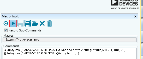
Option B: If the plug-in does not have this button, you'll need to execute a macro. You can copy the following text into a new text file, and save it with the “acemacro” file extension. Then load this macro file into the Macro Tools in ACE and run. Note that if you're using a different plug-in than AD9208, you'll need to swap out the chip name with what you're using in ACE.
-- Analog Devices, Inc. evaluation macro file
@Subsystem_1.ADS7-V2.AD9208 FPGA: Evaluation.Control.SetRegisterBit(0x106, 1, True, -1);
@Subsystem_1.ADS7-V2.AD9208 FPGA: @ApplySettings();
Be sure to click the Play button in the Macro Tools to execute the macro.
4. Go to the Analysis view in ACE and click Run Once.

5. Wait for falling edge (1.8V) output on SMA J6 (or wait long enough to ensure system is ready). At this time, ACE should be waiting for the FPGA to fill. You should see a Cancel button and the plot should not be refreshing.

6. Pulse trigger input or turn off input to 0V. Minimum pulse width of trigger is 640 divided by the serial line rate.
Once the trigger has been applied, ACE should capture and refresh the data onscreen.

resources/tools-software/ace/highspeedadctriggercapture.txt · Last modified: 07 Nov 2018 15:30 by Michael Sink