


This version is outdated by a newer approved version. This version (28 Feb 2018 19:53) was approved by Jeff Watson.
This version (28 Feb 2018 19:53) was approved by Jeff Watson.This is an old revision of the document!
Table of Contents
EV-HT-200CDAQ1 Test Summary
Extensive testing was performed on several EV-HT-200CDAQ1 boards to assess typical performance over temperature, along with a 200 hour temperature soak at 200°C ambient. The test results provided here are for guidance on typical performance only. A large sample size was not used during testing and results shown do not imply a guaranteed specification.
General Test Setup
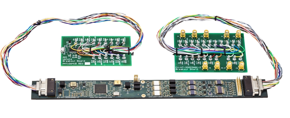
For testing over temperature, the EV-HT-200CDAQ1 was placed in a Tenny TUJR lab oven, capable of both heating to above 200°C and cooling below -40°C. Connections to the board were made through ports in the oven using the same breakout boards included in the EV-HT-200CDAQ1 kit. It should be noted that the connectors and harness on the breakout boards are suitable for high temperature exposure, but the breakout boards themselves are not, and they should never be collocated in a hot ambient environment with the main board.
Data was collected using the HT DAQ Viewer software (see the downloads page) and other lab instruments that are described in each individual test section.
All test results below were measured with +5VDC Vp /-2.5VDC Vm / +3.3VD power supplies. While a 3.3VD only power configuration is supported, the analog input range must be limited to about 1.0Vpp with 1.25V common mode for best performance, due to analog headroom requirements.
Power Consumption Profile
Average current consumption was measured on each power rail with digital multimeters. Power cycle testing was performed at each temperature point
A high power oscillator was used during the characterization phase of this project. This has been replaced in the final BOM with a lower power oscillator from the same manufacturer. The lower power oscillator saves approximately 7mA of current across the temperature range.


Crosstalk
Crosstalk, in simplified terms, is a metric of how much a channel in a data acquisition system is effected by signal(s) on adjacent channel(s). For more information on crosstalk in data converters, see this"Rarely Asked Questions" article.
For this test, a single board was used at room temperature. It was powered with +5VDC Vp/-2.5VDC Vm / +3.3VDC. A very low distortion signal generature was connected to a single channel at a time, AC coupled through a 3.3ųF capacitor. Unused channels were AC terminated to ground with a 3.3ųF capacitor. No multiplexer channels were switch during acquisition. The sample rate was set at 400ksps, and an 8192 point FFT was used for analysis, captured with the HT DAQ viewer software. The tables below show signal measurement in dBFS for 1kHz and 10kHz tone inputs. Channel to channel isolation is very good considering that signals are connected to the board with unshielded single ended wiring and pass through a Micro-D connector, which is not an connector optimized for signal integrity.


AC Characterization
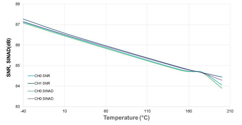
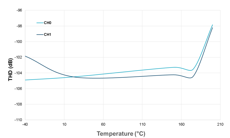
For this test, SNR and THD were measured on several boards over temperature. The boards were powered with +5VDC Vp /-2.5VDC Vm / +3.3VDC. A very low distortion signal generature was connected to a single channel at a time, 1.KHz tone, 2.4 Vpp, AC coupled through a 3.3ųF capacitor. Unused channels were AC terminated to ground with a 3.3ųF capacitor. No multiplexer channels were switch during acquisition. The sample rate was set at 400ksps, and an 8192 point FFT was used for analysis, captured with the HT DAQ viewer software. The plots below show SNR/SINAD and THD performance for non-multiplexed channels ADC0 and ADC1.
The screenshot below shows the HT DAQ Viewer Signal Analysis screen capture for the input tone while the board is soaking at 25°C, followed by a screen capture at 200°C
25°C Signal Analysis

200°C Signal Analysis

Multiplexed Inputs AC Performance
Multiplexed inputs tend introduce a higher level of complexity in the analog front end design and operation. With proper usage, the multiplexed inputs can obtain a similar level of performance as the ADC0 and ADC1 channels. However, there are several factors that must be considered when using the multiplexed inputs that significantly effect the input signal range and performance.
In the default configuration in which the EV-HT-200CDAQ1 board ships, the ADG798 multiplexer VSS pin is connected to ground. However, the ADG798 input requires about 1V headroom from the Vss, which becomes most apparent above 175°C. For this reason, jumper P3 is included on the board to attach the ADG798 to a negative rail. However, care must be taken not to exceed the ADG798 Vdd to Vss absolute maximum rating of 7.0V, or the Vss to ground rating of -3.5V. See the hardware design notes section for more information on power configuration options.
The plot below shows the performance that can be obtained from a multiplexed channel with ADG798 connected to ground, at 175°C. The input signal level has been reduced to -9dBFS. There is a corresponding decrease in SNR because of the decrease input signal level, but it is evident that other performance metrics still hold up. It should be reiterated that a negative voltage to the MUX VSS via P3 as described above that similar performance can be obtained with a full scale input signal as ADC0 and ADC1.
200°C Multipexed AC Performance, Reduced Signal Level
The second factor to keep in mind is the settling time when switching channels. Full sample rate is supported on this channel when switching between channels is not required. In multiplexed operation mode, adequate settling time needs to be provisioned depending on measurement accuracy requirements. For the default input channel configuration a settling of 5 time constants corresponds to a 3.3 ųs minimum sampling period.
Temperature Soak
In order to assess long term performance of the EV-HT-200CDAQ1, 2 boards were soaked for 200 hours at 200°C. One board was powered, one board was unpowered. A performance benchmark was taken at room temperature on both boards before the test. The powered unit was continuously running a measurement with the HT DAQ Viewer software and periodically power cycled. The powered unit functioned as expected during the soak test and through power cycles. After 200 hours, both boards were brought back down to room temperature and a functional test was run again. Both boards passed functional test and there was no notable change in performance. A picture of both board post temperature soak is shown below.

resources/eval/user-guides/high-temp/testreport.1519843998.txt.gz · Last modified: 28 Feb 2018 19:53 by Jeff Watson