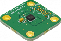
The EVAL-ADXL312Z, EVAL-ADXL313Z, and EVAL-ADXL314Z are simple breakout boards that enable easy connection of the mounted accelerometer into an existing system.

The breakout boards has to be supplied with a power between 2.0 and 3.6V. The host system should be capable of providing a 3.3V supply.
| P1 Pin Number | Pin Function | Mnemonic |
|---|---|---|
| Pin 1 | Supply Voltage | VS |
| Pin 2 | Digital Interface Supply Voltage | VDDIO |
| Pin 3 | Not Connected | NC |
| Pin 4 | Not Connected | NC |
| Pin 5 | Serial Data Output | SDO |
| Pin 6 | Serial Data Input | SDI |
| Pin 7 | Serial Communications Clock | SCLK |
| Pin 8 | Chip Select | CS |
| Pin 9 | Ground | GND |
| Pin 10 | Interrupt 1 Output | INT1 |
The goal of ADI Microcontroller No-OS is to be able to provide reference projects for lower end processors, which can't run Linux, or aren't running a specific operating system, to help those customers using microcontrollers with ADI parts. ADI No-OS offers generic drivers which can be used as a base for any microcontroller platform and also example projects which are using these drivers on various microcontroller platforms.
For more information about ADI No-OS and supported microcontroller platforms see: no-OS.
Information about the ADXL313 driver can be found here: ADXL313 driver.
Make sure that you specify the correct device type (ID_ADXL31x) during initialization, so that it matches the device one on your breakout board or in your system.
struct adxl313_init_param adxl313_user_init = {
        .dev_type = ID_ADXL313,
        .comm_type = ADXL313_SPI_COMM,
}
The following table shows how the connection between the accelerometer breakout board and NUCLEO-F401RE used in this project example.
| Pin No. | NUCLEO-F401RE Pin | Function (breakout board) | Mnemonic |
|---|---|---|---|
| Pin 1 | POWER 3.3V | Supply Voltage | VD |
| Pin 2 | POWER 3.3V | Digital Intf. Supply Voltage | VDDIO |
| Pin 5 | PA6 | Serial Data Output | SDO |
| Pin 6 | PA7 | Serial Data Input | SDI |
| Pin 7 | PB3 | Serial Clock | SCLK |
| Pin 8 | PA4 | Chip Select | CS |
| Pin 9 | GND | Ground | GND |
| Pin 10 | PA10 | Interrupt 1 | INT1 |
In order to build the basic project make sure you have the following configuration in the Makefile:
# Select the example you want to enable by choosing y for enabling and n for disabling
BASIC_EXAMPLE = y
IIO_EXAMPLE = n
When running make command make sure to specify the platform you want to build the project for.
The basic project contains the generic HAL initialization of the used platform, together with the SPI and UART driver configuration and initialization.
The SPI driver is used to communicate with the device on the breakout board, while the UART driver is used to display on the host machine the measured data.
The basic project contains the ADXL313 driver initialization in 3-Wire SPI mode, performs a self-test routine for the device, configures the device, and periodically lists the contents of the FIFO in the terminal via a serial connection.
The code is available here.
UART Output:
Single read raw data:
 x=-66 y=-10 z=114
Single read:
 x=-5.56553898 y=0.689530077 z=8.887276548
Number of read entries from the FIFO 32.
 x=  -4.979939445 m/s^2 y=   0.766144530 m/s^2 z=   8.734047642 m/s^2
 x=  -5.056553898 m/s^2 y=   0.766144530 m/s^2 z=   8.657433189 m/s^2
 x=  -5.056553898 m/s^2 y=   0.766144530 m/s^2 z=   8.734047642 m/s^2
 x=  -4.979939445 m/s^2 y=   0.689530077 m/s^2 z=   8.657433189 m/s^2
 x=  -5.056553898 m/s^2 y=   0.689530077 m/s^2 z=   8.734047642 m/s^2
 x=  -5.056553898 m/s^2 y=   0.689530077 m/s^2 z=   8.734047642 m/s^2
 x=  -5.056553898 m/s^2 y=   0.689530077 m/s^2 z=   8.657433189 m/s^2
 x=  -5.056553898 m/s^2 y=   0.766144530 m/s^2 z=   8.734047642 m/s^2
 x=  -5.056553898 m/s^2 y=   0.689530077 m/s^2 z=   8.657433189 m/s^2
 x=  -5.133168351 m/s^2 y=   0.689530077 m/s^2 z=   8.734047642 m/s^2
 x=  -5.056553898 m/s^2 y=   0.689530077 m/s^2 z=   8.734047642 m/s^2
 x=  -5.056553898 m/s^2 y=   0.689530077 m/s^2 z=   8.734047642 m/s^2
 x=  -5.056553898 m/s^2 y=   0.689530077 m/s^2 z=   8.734047642 m/s^2
 x=  -5.056553898 m/s^2 y=   0.689530077 m/s^2 z=   8.734047642 m/s^2
 x=  -5.056553898 m/s^2 y=   0.689530077 m/s^2 z=   8.810662095 m/s^2
 x=  -5.056553898 m/s^2 y=   0.689530077 m/s^2 z=   8.734047642 m/s^2
 x=  -4.979939445 m/s^2 y=   0.689530077 m/s^2 z=   8.734047642 m/s^2
 x=  -5.056553898 m/s^2 y=   0.689530077 m/s^2 z=   8.734047642 m/s^2
 x=  -5.056553898 m/s^2 y=   0.766144530 m/s^2 z=   8.734047642 m/s^2
 x=  -5.056553898 m/s^2 y=   0.689530077 m/s^2 z=   8.734047642 m/s^2
 x=  -5.056553898 m/s^2 y=   0.612915624 m/s^2 z=   8.734047642 m/s^2
 x=  -5.056553898 m/s^2 y=   0.689530077 m/s^2 z=   8.810662095 m/s^2
 x=  -5.056553898 m/s^2 y=   0.689530077 m/s^2 z=   8.657433189 m/s^2
 x=  -5.056553898 m/s^2 y=   0.689530077 m/s^2 z=   8.734047642 m/s^2
 x=  -5.133168351 m/s^2 y=   0.689530077 m/s^2 z=   8.734047642 m/s^2
 x=  -5.056553898 m/s^2 y=   0.689530077 m/s^2 z=   8.734047642 m/s^2
 x=  -5.056553898 m/s^2 y=   0.689530077 m/s^2 z=   8.734047642 m/s^2
 x=  -5.056553898 m/s^2 y=   0.766144530 m/s^2 z=   8.734047642 m/s^2
 x=  -5.056553898 m/s^2 y=   0.689530077 m/s^2 z=   8.657433189 m/s^2
 x=  -5.056553898 m/s^2 y=   0.689530077 m/s^2 z=   8.657433189 m/s^2
 x=  -5.056553898 m/s^2 y=   0.689530077 m/s^2 z=   8.734047642 m/s^2
 x=  -4.979939445 m/s^2 y=   0.766144530 m/s^2 z=   8.657433189 m/s^2
==========================================================
Interrupt sources:
DATA_READY event flag = 1.
ACTIVITY event flag = 0.
INACTIVITY event flag = 1.
WATERMARK event flag = 1.
OVERRUN event flag = 1.
===========================================================
In order to build the IIO project make sure you have the following configuration in the Makefile:
# Select the example you want to enable by choosing y for enabling and n for disabling
BASIC_EXAMPLE = n
IIO_EXAMPLE = y
When running make command make sure to specify the platform you want to build the project for.
This project is actually a TINYIIOD demo for the used breakout board (the code is available here.). The project launches a TINYIIOD server on the board so that the user may connect to it via an IIO client. Using IIO-Oscilloscope, the user can configure the accelerometer and view the measured data on a plot.
If you are not familiar with ADI IIO Application, please take a look at: IIO No-OS.
This IIO Project uses IIO-Oscilloscope as a client. If you are not familiar with ADI IIO-Oscilloscope Client, please take a look at: IIO Oscilloscope .
The No-OS IIO Application together with the No-OS IIO ADXL313 driver take care of all the backend logic needed to setup the IIO server. The user has to initialize the IIO device and call the IIO app as shown below. The read buffer is used for storing data which will be available on the plot in the IIO Oscilloscope Client.
struct adxl313_iio_dev *adxl313_iio_desc;
struct adxl313_iio_dev_init_param adxl313_init_par;

adxl313_init_par.adxl313_dev_init = &adxl313_user_init;
ret = adxl313_iio_init(&adxl313_iio_desc, &adxl313_init_par);
if (ret)
	return ret;

switch(adxl313_iio_desc->adxl313_dev->dev_type) {
case ID_ADXL312:
	dev_name = "ADXL312";
	break;
case ID_ADXL313:
	dev_name = "ADXL313";
	break;
case ID_ADXL314:
	dev_name = "ADXL314";
	break;
default:
	return -ENODEV;
}

	struct iio_app_device iio_devices[] = {
		{
			.name = dev_name,
			.dev = adxl313_iio_desc,
			.dev_descriptor = adxl313_iio_desc->iio_dev,
		}
	};

	return iio_app_run(iio_devices, NO_OS_ARRAY_SIZE(iio_devices));
After flashing and running the application, IIO Oscilloscope can be used to make the desired configuration and obtain the desired data. Snippets from IIO Oscilloscope, when running the IIO Project, follow.
Below you can see the Connection window for IIO Oscilloscope. The handshake is performed and the device is detected over UART. After pressing the Connect button we can see the device in the list, together with its channels and we can see the measured data.

Below you can see the Simple View which contains the read data from the accelerometer. Observe how the measurements change. The accelerometer is positioned such that the gravitational force is first perpendicular on its XY plane. In this case the measured acceleration on Z axis is ~g and the measured acceleration on X and Y axis is ~ 0. The accelerometer is then positioned such that the gravitational force is perpendicular on its XZ plane. In this case the measured acceleration on Y axis is ~g, on X and Z axis is ~ 0). The device used for this example is an ADXL314. Finally, the accelerometer is positioned such that the gravitation force is perpendicular on its YZ plane. In this case the measured acceleration on on X axis is ~g and the measured acceleration on Y and Z axis is ~0.
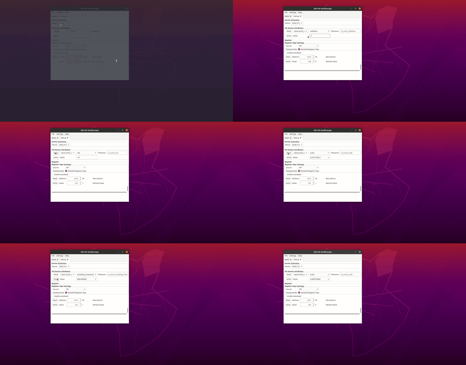
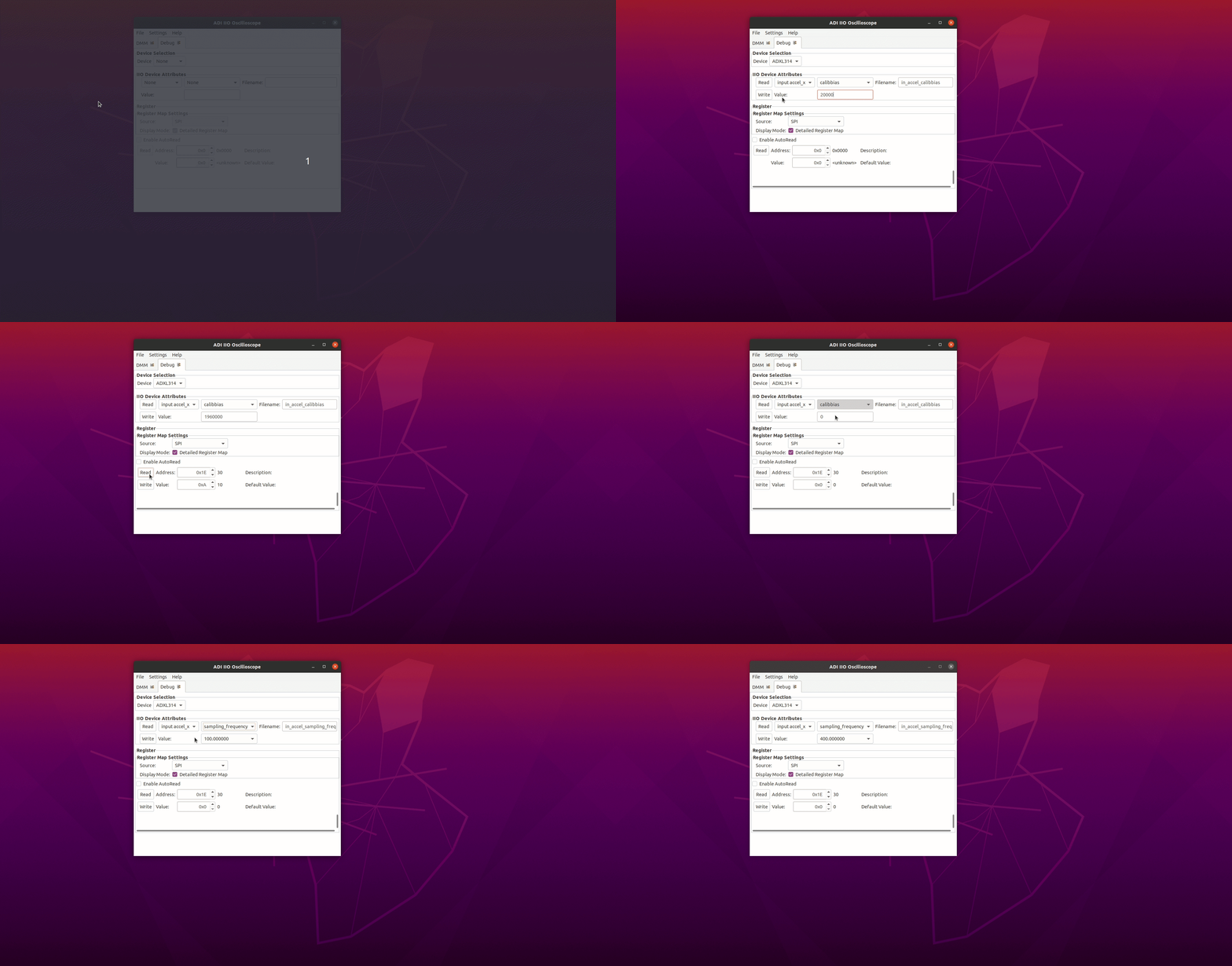
Below you can see the Debug View which contains the list of attributes for each channel of the selected device. Some attributes, like the calibbias, range, sampling frequency, scale (applicable only for ADXL312 and ADXL313) can be changed by the user, while the other attributes can be just read. You may also observe that some attributes of the acceleration channels are shared in value, range, sampling frequency, and scale, while calibbias and raw attributes may have different value for each acceleration channel.

Range and scale cannot be changed for ADXL314.

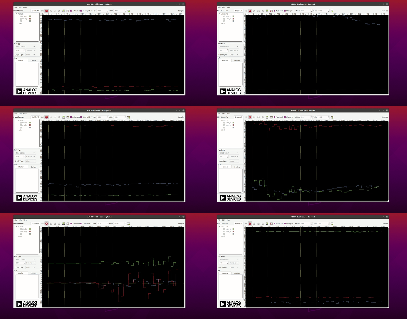
Below you can see the Plot View for the acceleration data. The Plot view shows the raw vales measured by the accelerometer. In this case the device is moved such that the gravitational force is perpendicular on XY, XZ and YZ planes. You may observe the spikes in the data due to the sudden change of the accelerometer.
