


This version is outdated by a newer approved version. This version (14 Jan 2021 05:32) was approved by Robin Getz.The Previously approved version (12 Dec 2017 21:37) is available.
This version (14 Jan 2021 05:32) was approved by Robin Getz.The Previously approved version (12 Dec 2017 21:37) is available.This is an old revision of the document!
Table of Contents
PMOD Accelerometer Demo
The ADuCM360_demo_pmodacl2 is an accelerometer demo project for the EVAL-ADICUP360 base board with additional PmodACL2 PMOD which is manufactured by Digilent, using the GNU ARM Eclipse Plug-ins in Eclipse environment.
General description
This project is an example for how to use EVAL-ADICUP360 board in combination with the PmodACL2 accelerometer PMOD.
The ADuCM360_demo_pmodacl2 project uses the PmodACL2 PMOD which has the ADXL362 3-axis MEMS accelerometer on board.

The application reads the X , Y , and Z acceleration registers. The acceleration in the 3 axis is displayed in [mG]. There is also an internal temperature sensor in the ADXL362, which is read and out either in [C] or [codes]. This is set by changing the TEMP_ADC variable within the main.c file. (Value of [0] is degrees Celsius, and value [1] is ADC codes) The acceleration range can also be selected by setting the ADXL_SENSE variable with the main.c file. (Values of [2, 4, and 8 are acceptable] )
All the outputs are printed from the UART to the USER USB port and can be read on the PC using a serial terminal program, such as Putty or Tera Term.
For precision applications, each ADXL362 chip requires individual calibration which can be done by measuring and setting the definitions ACC_TEMP_BIAS and ACC_TEMP_SENSITIVITY parameters in the ADXL362.h file.
The temperature in degrees celsius, Treal , can be derived from the ADC readings Tadc using the predefined formula:
Treal = (Tadc + ACC_TEMP_BIAS)/(1 / ACC_TEMP_SENSITIVITY)
Demo Requirements
The following is a list of items needed in order to replicate this demo.
- Hardware
- EVAL-ADICUP360
- PmodAcl2
- Mirco USB to USB cable
- PC or Laptop with a USB port
- Software
- ADuCM360_demo_pmodacl2 software
- CrossCore Embedded Studio (2.7.0 or higher)
- ADuCM36x DFP (1.0.2 or higher)
- CMSIS ARM Pack (4.3.0 or higher)
Setting up the hardware
- To program the base board, set the jumpers as shown in the next figure. The important jumpers are highlighted in red.
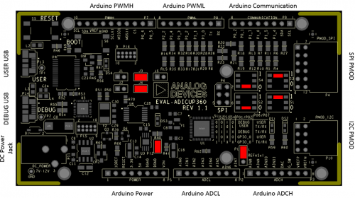
- Plug the PmodACL2 PMOD in the EVAL-ADICUP360 base board, via the PMOD_SPI port (P4).
- Power EVAL-ADICUP360 base board via the DEBUG USB port (P14).

Obtaining the source code
We recommend not opening the project directly, but rather import it into CCES and make a local copy in your workspace.
The source code and include files of the ADuCM360_demo_pmodacl2 can be found on Github:
CrossCore Embedded Studio Application Source Code:
AduCM360_demo_pmodacl2 at Github
For more information on importing, debugging, or other tools related questions, please see the tools user guide.
Configuring the Software Parameters
Configure the ADXL362 full scale acceleration range in the main.c file.
#define ADXL_SENSE 2 /* Values of 2, 4, or 8 are acceptable [g] range */
Configure the temperature units in the ADXL362.h file.
#define TEMP_ADC 1 /* 0 for ADC units or 1 for Celsius degrees */
Configure the ADXL362 Calibration Values in the ADXL362.h file. These values will vary from sensor to sensor, but these are typical values from the datasheet.
#define ACC_TEMP_BIAS             (float)350
#define ACC_TEMP_SENSITIVITY      (float)0.065
Set the Accelerometer Scan Time in the ADXL362.h file. This is how often you read your axis and temperature data.(in ms)
#define SCAN_SENSOR_TIME 500
Set the activity and inactivity thresholds for the ADXL362 in the ADXL362.h file. These values are used to determine which acceleration values the sensor can react at sleep/wake-up commands.(in mG)
#define ACT_VALUE          50
#define INACT_VALUE        50
Set the activity and inactivity time for the ADXL362 in the ADXL362.h file. These values are used to determine sleep/wake-up intervals.(in ms)
#define ACT_TIMER          50
#define INACT_TIMER        50
Configure the Chip Select(CS) Pin for the ADXL362 in the Communication.h file. Position of P9 header
#define ADXL_CS_SEL CSACC_PIN_P0_4 /* CSACC_PIN_P0_3 or CSACC_PIN_P0_4 */
Configure the Interrupt Pin from the ADXL362 in the Communication.h file. Position of P7 header
#define ADXL_INT_SEL INTACC_PIN_1 /* INTACC_PIN_1 or INTACC_PIN_2 */
Configure the Chip Select(CS) Pin for the LCD Screen in the Communication.h file. Position of P8 header
#define LCD_CS_SEL CSLCD_PIN_P1_4 /* CSLCD_PIN_P2_2 or CSLCD_PIN_P1_4 */
Configure the Reset Pin from the LCD Screen in the Communication.h file. Position of P6 header
#define LDC_RST_SEL RSLCD_PIN_IOREF /* RSLCD_PIN_IOREF or RSLCD_PIN_P1_1 */
Outputting Data
Serial Terminal Output
- In order to view the data, you must flash the program to the EVAL-ADICUP360.
- Once complete you will need to switch the USB cable from the DEBUG USB (P14) to the USER USB (P13).
- Then follow the UART settings below with the serial terminal program.
Following is the UART configuration.
  Select COM Port
  Baud rate: 9600
  Data: 8 bit
  Parity: none
  Stop: 1 bit
  Flow Control: none
The user must press the <ENTER> key each time they want to display the results.
How to use the Tools
The official tool we promote for use with the EVAL-ADICUP360 is CrossCore Embedded Studio. For more information on downloading the tools and a quick start guide on how to use the tool basics, please check out the Tools Overview page.
Importing
For more detailed instructions on importing this application/demo example into the CrossCore Embedded Studios tools, please view our How to import existing projects into your workspace section.
Debugging
For more detailed instructions on importing this application/demo example into the CrossCore Embedded Studios tools, please view our How to configure the debug session section.
Project structure
The ADuCM360_demo_pmodacl2 project use basic ARM Cortex-M C/C++ Project structure.
This project contains: system initialization part - disabling watchdog, setting system clock, enabling clock for peripheral; port configuration for SPI0, accelerometer sensor use; SPI read/write functions; sensor monitoring.

In the src and include folders you will find the source and header files related to pmodacl2 application. You can modify as you wanted those files. The Communication.c/h files contain SPI and UART specific data, meanwhile the ADXL362.c/h files contain the accelerometer data. Here are parameters you can configure:
The RTE folder contains device and system related files:
- Device Folder – contains low levels drivers for ADuCM360 microcontroller.(try not to edit these files)
- system.rteconfig - Allows the user to select the peripherial components they need, along with the startup and ARM cmsis files needed for the project.
End of Document
resources/eval/user-guides/eval-adicup360/reference_designs/demo_pmodacl2.1610598244.txt.gz · Last modified: 14 Jan 2021 05:24 by Robin Getz