


This version is outdated by a newer approved version. This version (16 Mar 2018 19:16) was approved by Brandon Bushey.
This version (16 Mar 2018 19:16) was approved by Brandon Bushey.This is an old revision of the document!
Table of Contents
This page is currently under development and is NOT final yet. We are not trying to mislead anyone with the content on this page, but it's important to note that the information on this page can change at any time.
Turbidity Measurement Demo (with EVAL-CN0409-ARDZ)
The EVAL-CN0409-ARDZ shield is a low to high level water turbidity measurement system in combination with the EVAL-ADICUP360. It uses the ADPD105's ambient light rejection feature to make it ideal for applications where accurate, robust and non-contact turbidity measurements are critical.

General description
The ADuCM360_demo_cn0409
Calibration procedure
When the project is being run for the first time a calibration procedure is required in order to achieve high accuracy results. The user must follow the steps described in the UART terminal when the application is started.
Demo Requirements
The following is a list of items needed in order to replicate this demo.
- Hardware
- EVAL-ADICUP360
- EVAL-CN0409-ARDZ Evaluation Board
- Mirco USB to USB cable
- PC or Laptop with a USB port
- Test Vials
- Turbidity Calibration Solutions (0.02FTU,100FTU and 800FTU)
- Turbidity Solutions (10FTU,15FTU,10FTU,100FTU and 1000FTU)
The turbidity calibration solutions used in the evaluation are the HI88703-11,Oakton T100 and Cole Parmer kit
- Software
- ADuCM360_demo_cn0409 software
- CrossCore Embedded Studio (2.7.0 or higher)
- ADuCM36x DFP (1.0.2 or higher)
- CMSIS ARM Pack (4.3.0 or higher)
- Serial Terminal Program
- Such as Putty or Tera Term
Setting up the hardware
Test Setup Functional Block Diagram

Test Vial Considerations
To obtain a most accurate results when taking measurements, process below should take into considerations:
- Test vials must be meticulously cleaned. Cleaning involves washing the vials with soap and deionized water, soaking the sample vial in Hydrochloric Acid solution, rinsing with ultra-filtered deionized water, and polishing with silicone oil.
- Test vials must also be indexed. After the cleaning process, the vial is used to measure a very low turbidity solution. The position with the lowest measured turbidity should be indexed and this position should be used for succeeding measurements.
- Remove bubbles in the solution. This can be done by letting the solution stand for several minutes to allow the bubbles to vacate.
- If possible, use one properly indexed test vial.
It is recommended to use LaMotte Test Vial as the size fits into the on board vial holder
Measurement Procedure
- Fill a clean test vial up to 10mL of the solution under test
- Allow sufficient time for bubbles to escape before placing the cap
- Wipe the test vial with a lint free cloth before inserting into the on board test vial holder to make sure it is free from fingerprints.
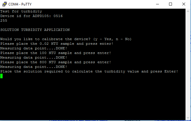
- Open putty software and hit reset button on EVAL-ADICUP360. Follow on screen prompt for the calibration as shown below.


For first time use, it is required to perform calibration by typing y key. For the succeeding measurements, just hit n key to skip calibration
- 3-point calibration will perform using 0.02FTU,100 FTU and 800 FTU. Wait for the onscreen prompt before placing each solution.

- After calibration, place the solution required to measure turbidity as prompted on the screen.
- For more details on the software, visit CN0409 Software User Guide.


Make sure you are holding on the test vial cap when placing on the holder

Obtaining the source code
We recommend not opening the project directly, but rather import it into CCES and make a local copy in your workspace.
The source code and include files of the ADuCM360_demo_cn0409 can be found on Github:
CrossCore Embedded Studio Application Source Code:
AduCM360_demo_cn0338 at Github
For more information on importing, debugging, or other tools related questions, please see the tools user guide.
Outputting Data
Serial Terminal Output
- In order to view the data, you must flash the program to the EVAL-ADICUP360.
- Once complete you will need to switch the USB cable from the DEBUG USB (P14) to the USER USB (P13).
- Then follow the UART settings below with the serial terminal program.
Following is the UART configuration.
  Select COM Port
  Baud rate: 9600
  Data: 8 bit
  Parity: none
  Start: 1 bit
  Stop: 2 bit
  Flow Control: none
How to use the Tools
The official tool we promote for use with the EVAL-ADICUP360 is CrossCore Embedded Studio. For more information on downloading the tools and a quick start guide on how to use the tool basics, please check out the Tools Overview page.
Importing
For more detailed instructions on importing this application/demo example into the CrossCore Embedded Studios tools, please view our How to import existing projects into your workspace section.
Debugging
For more detailed instructions on importing this application/demo example into the CrossCore Embedded Studios tools, please view our How to configure the debug session section.
Project structure
 The ADuCM360_demo_cn0409 is a C++ project that uses ADuCM36x C/C++ Project structure.
This project contains: system initialization part, setting system clock, enabling clock for peripherals; i2c interface, UART via P0.6/P0.7; UART read/write functions; Memory read/write functions; turbidity calculations;
In the src and include folders you will find the source and header files related to CN0409 software application. The Communication.cpp/h files contain UART and I2C specific data, meanwhile the CN0409.cpp/h files contain the calculation part and Flash.cpp/h provide memory management. .
End of Document
resources/eval/user-guides/eval-adicup360/reference_designs/demo_cn0409.1521224196.txt.gz · Last modified: 16 Mar 2018 19:16 by Brandon Bushey