


This version is outdated by a newer approved version. This version (14 Jan 2021 05:32) was approved by Robin Getz.The Previously approved version (03 Jan 2021 21:46) is available.
This version (14 Jan 2021 05:32) was approved by Robin Getz.The Previously approved version (03 Jan 2021 21:46) is available.This is an old revision of the document!
Table of Contents
Soil Measurements for pH and moisture Demo
The ADuCM360_demo_cn0398 is a pH and moisture measurements demo project, for the EVAL-ADICUP360 base board with additional EVAL-CN0398-ARDZ shield, created using the GNU ARM Eclipse Plug-ins in Eclipse environment.
General description
The ADuCM360_demo_cn0398 project uses the EVAL-CN0398-ARDZ shield which is a single supply, low power, high precision complete solution for soil moisture and pH measurements, including temperature compensation. The circuit is optimized for capacitive soil moisture sensors that are insensitive to water salinity and do not corrode over time. The circuit also measures soil pH so it increases the range of applications where this shield can be used.
The circuit is divided into three independent measurement front ends: pH, soil moisture, and temperature. After signal conditioning, the three channels share an AD7124-8, 24-bit sigma-delta (Σ-Δ) ADC. The AD7124-8, is a low power, low noise, completely integrated analog front end for high precision measurement applications.
 The board offers the possibility to configure Vin supply voltage (P10 connector) in order to use 5V or 7V-12V. Considering moisture sensor which is used, the P8 connector configure 3.3V or 5V supply. The user has the possibility to select one of the three GPIOs available for ADC CS pin using P5 connector (default configuration for P5 is 1-2 position). For temperature compensation can be used an RTD PT100 sensor, 2-wire (this is used in the demo), 3-wire or 4-wire connection (see P1 connector). For this demo was used for the moisture measurement the VH400 sensor (P2) and for pH measurement Atlas Scientific sensor (J1). The DS1 LED is ON as long the pH value is measured and calculated and the DS3 is ON as long as the moisture value is measured and calculated.
The ADuCM360_demo_cn0398 application processes ADC outputs for all 3 channels (RTD, pH and moisture), calculates pH and moisture values using as input RTD temperature value. Those data are sent to serial interface, usig UART communication (115200 baud rate and 8-bits data length). The 24-bits ADC data are received using SPI interface of the EVAL-ADICUP360 board.
The board offers the possibility to configure Vin supply voltage (P10 connector) in order to use 5V or 7V-12V. Considering moisture sensor which is used, the P8 connector configure 3.3V or 5V supply. The user has the possibility to select one of the three GPIOs available for ADC CS pin using P5 connector (default configuration for P5 is 1-2 position). For temperature compensation can be used an RTD PT100 sensor, 2-wire (this is used in the demo), 3-wire or 4-wire connection (see P1 connector). For this demo was used for the moisture measurement the VH400 sensor (P2) and for pH measurement Atlas Scientific sensor (J1). The DS1 LED is ON as long the pH value is measured and calculated and the DS3 is ON as long as the moisture value is measured and calculated.
The ADuCM360_demo_cn0398 application processes ADC outputs for all 3 channels (RTD, pH and moisture), calculates pH and moisture values using as input RTD temperature value. Those data are sent to serial interface, usig UART communication (115200 baud rate and 8-bits data length). The 24-bits ADC data are received using SPI interface of the EVAL-ADICUP360 board.

The temperature value is calculated based on the RTD resistance:
                                                               CODE - ADC output
       Rrtd = ((CODE - 2^23)* Rref)/GAIN*2^23                  Rref - Reference resistor (5kΩ)
                                                               GAIN - used gain for RTD channel (16)
1. RTD resistance > 100Ω

2. RTD resistance ≤ 100Ω

The pH value can be calculated in two ways, so user can configure which one did he want for his application: using two-point calibration data or using Nernst equation. After initialization the user will be asked in the terminal window if he want to perform pH calibration → in this case the pH value will be calculated using calibration measured value:
                                                    y1 - measured voltage at calibration point 1 for known pH
                                                    y2 - measured voltage at calibration point 2 for known pH
        pH = [m*(V -y2 + Voffset) + x2]             x1 - known pH at calibration point 1
                                                    x2 - known pH at calibration point 2
        m  = [(x2-x1)/(y2-y1)]                      V - pH channel measured voltage
                                                    Voffset - Offset voltage
A default calibration package can be loaded (in case is not wanted to perform calibration everytime). For this is needed to update default_calibration_ph array with known values before the board is program. In case the two-point calibration is not wanted, for pH calculation is used Nernst equation:
      ph  = [PH_ISO -((V - a) / ((2.303 * AVOGADRO * (T + 273.1))]

      PH_ISO - reference hydrogen ion concentration (7)
      V - pH channel measured voltage
      a - zero point tolerance (see //ZERO_POINT_TOLERANCE// parameter)
      AVOGADRO - Avogadro's number (8.314)
      T - RTD temperature
The moisture value can be also calculated in two ways. First way is to use piece-wise formulas given by manufacturer (check USE_MANUFACTURER_MOISTURE_EQ parameter. For Vegetronix may use the follow formulas (m - moisture value and Vm - moisture channel measured voltage):
| Voltage Range | Equation |
|---|---|
| 0V - 1.1V | m = 10 * Vm - 1 |
| 1.1V - 1.3V | m = 25 * Vm - 17.5 |
| 1.3V - 1.82V | m = 48.08 * Vm - 47.5 |
| 1.82V - 2.2V | m = 26.32 * Vm - 7.89 |
Otherwise the moisture value can be calculated using transfer function for the sensor:
m =-1.18467 + 21.5371*Vm - 110.996*Vm^2 + 397.025*Vm^3 - 666.986*Vm^4 + 569.236*Vm^5 -246.005*Vm^6 + 49.4867*Vm^7 -3.37077*Vm^8
Demo Requirements
The following is a list of items needed in order to replicate this demo.
- Hardware
- EVAL-ADICUP360
- EVAL-CN0398-ARDZ
- pH probe with BNC connector
- Analog Moisture sensor
- PT100 RTD Probe
- 7V to 12V DC Power Supply
- Mirco USB to USB cable
- PC or Laptop with a USB port
- Software
- ADuCM360_demo_cn0398 software
- CrossCore Embedded Studio (2.7.0 or higher)
- ADuCM36x DFP (1.0.2 or higher)
- CMSIS ARM Pack (4.3.0 or higher)
- Serial Terminal Program
- Such as Putty or Tera Term
Video
All About Circuits created a video showing users how they can use the moisture sensor portion of the CN0398 to monitor the water level of your household plants. Check it out!
Setting up the hardware
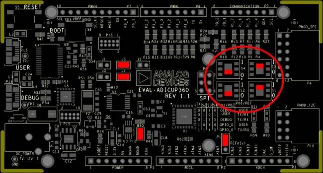
- To program the base board, set the jumpers/switches as shown in the next figure. The important jumpers/switches are highlighted in red.
- Connect the EVAL-CN0398-ARDZ to the Arduino connectors P2, P5, P6, P7, P8 of the EVAL-ADICUP360 board.
- Connect the pH sensor to the J1 connector of the EVAL-CN0398-ARDZ.
- Connect the RTD sensor to the P1 connector of the EVAL-CN0398-ARDZ.(see connection details)
- Connect the moisture sensor to the P2 connector of the EVAL-CN0398-ARDZ.(see connection details)

Extremely important to plug in an acceptable power supply to the barrel jack P11 of the EVAL-ADICUP360 if you are using a moisture sensor that requires voltage excitation greater than 5V on the EVAL-CN0398-ARDZ. Only moisture sensors using less than 3.3V can run off the USB power option.
- Set the jumpers on the EVAL-CN0398-ARDZ to the position shown below.
 (need picture)
 - Plug in the USB cable from the PC to the EVAL-ADICUP360 base board via the Debug USB.(P14)
Obtaining the source code
We recommend not opening the project directly, but rather import it into CCES and make a local copy in your workspace.
The source code and include files of the ADuCM360_demo_cn0398 can be found on Github:
CrossCore Embedded Studio Application Source Code:
AduCM360_demo_cn0398 at Github
For more information on importing, debugging, or other tools related questions, please see the tools user guide.
Configuring the Software Parameters
- Zero point tolerance - ZERO_POINT_TOLERANCE parameter - used in Nerst equation - input voltage value in [V] (CN0398.h).
- Terminal refresh - DISPLAY_REFRESH parameter - how often to refresh the output data - input time value in [msec] (CN0398.h).
- Moisture calculation formula - USE_MANUFACTURER_MOISTURE_EQ parameter - which formula to use in order to calculate the moisture value - commented → transfer function, uncommented → manufacturer formulas(CN0398.h).
Outputting Data
Serial Terminal Output
- In order to view the data, you must flash the program to the EVAL-ADICUP360.
- Once complete you will need to switch the USB cable from the DEBUG USB (P14) to the USER USB (P13).
- Then follow the UART settings below with the serial terminal program.
Following is the UART configuration.
  Select COM Port
  Baud rate: 115200
  Data: 8 bit
  Parity: none
  Stop: 1 bit
  Flow Control: none
- The software will ask if you want to do a calibration, so type in [n] or [y].
- If [n] is selected, the software will ask if you would like to load the default configuration, or use the Nernst equations. Select one option.
- The data output refreshes in the console window at the rate of the “display_refresh” parameter with the following results.
How to use the Tools
The official tool we promote for use with the EVAL-ADICUP360 is CrossCore Embedded Studio. For more information on downloading the tools and a quick start guide on how to use the tool basics, please check out the Tools Overview page.
Importing
For more detailed instructions on importing this application/demo example into the CrossCore Embedded Studios tools, please view our How to import existing projects into your workspace section.
Debugging
For more detailed instructions on importing this application/demo example into the CrossCore Embedded Studios tools, please view our How to configure the debug session section.
Project Structure
The ADuCM360_demo_cn0398 is a C++ project that uses ADuCM36x C/C++ Project structure.
This project contains: system initialization part - disabling watchdog, setting system clock, enabling clock for peripherals; port configuration for ADC, SPI read/write; for configuring and reading from AD7124, UART via P0.6/P0.7; UART read/write functions; for calibration and displaying the results.

In the src and include folders you will find the source and header files related to CN0398 software application. The Communication.cpp/h files contain SPI and UART specific data, meanwhile the CN0398.cpp/h files contain the calculation part, the AD7124.c/h files contain ADC channels handling.
The pH calibration parameters are set at the run time, after initialization in the terminal window will appear information messages how to perform calibration part.
The RTE folder contains device and system related files:
- Device Folder – contains low levels drivers for ADuCM360 microcontroller.(try not to edit these files)
- system.rteconfig - Allows the user to select the peripherial components they need, along with the startup and ARM cmsis files needed for the project.
End of Document
resources/eval/user-guides/eval-adicup360/reference_designs/demo_cn0398.1610598243.txt.gz · Last modified: 14 Jan 2021 05:24 by Robin Getz