


This version is outdated by a newer approved version. This version (14 Jan 2021 05:32) was approved by Robin Getz.The Previously approved version (03 Jan 2021 21:46) is available.
This version (14 Jan 2021 05:32) was approved by Robin Getz.The Previously approved version (03 Jan 2021 21:46) is available.This is an old revision of the document!
Table of Contents
Smart Visible Light Detection Demo
The ADuCM360_demo_cn0397 is a RGB light detection demo project for the EVAL-ADICUP360 base board with additional EVAL-CN0397-ARDZ shield, created using the GNU ARM Eclipse Plug-ins in Eclipse environment.
General description
The ADuCM360_demo_cn0397 project uses the EVAL-CN0397-ARDZ shield which is a single-supply, low power, low noise, 16-bit light detector utilizing wavelength specific photodiodes. The photodiodes used in this circuit are sensitive at different wavelengths, to read light intensity levels over the visible light spectrum where the plants are photosynthetically active.
The EVAL-CN0397-ARDZ board uses AD8500, a low power, precision CMOS op amp with a low input bias current of a typical 1pA which is used in a transipedance amplifier configuration to convert the current output of the photodiodes into voltage. It also features AD7798 a 3-channel, low noise, low power 16-bit ADC that converts the analog voltage into digital data in for the processing of data into light intensity. The circuit utilizes RGB photodiodes from Everlight with their peak sensitivities 620nm (R), 550nm (G) and 470nm (B).
The ADuCM360_demo_cn0397 application perform ADC readings for all 3 channels, processes them and make all necessary calculations in order to provide light intensity and light concentration for each color.

The 16-bits ADC data are received using SPI interface of the EVAL-ADICUP360 board. The UART interface (115200 baud rate and 8-bits data length) is used to send(and to receive) data to (from) a terminal window.
Light intensity [Lux] is calculated using ADC output value for selected channel and a constant value for each color:
Light Intensity = CODE * Light intensity Constant
Light Concentration [%] is calculated based on the light intensity and optimal level for each color:
Light concentration = Intensity*100/Optimal Level
Beside light intensity and light concentration values, for each channel will be displayed a colored bar in [0%, 100%] format for light concentration representation. It will inform the user when the concentration for a specific channel will reach 100%. Application offer the possibility to perform a system offset calibration for each RGB channel. All calculation are using data specific to each color of the used LEDs:

Demo Requirements
The following is a list of items needed in order to replicate this demo.
- Hardware
- EVAL-ADICUP360
- EVAL-CN0397-ARDZ
- Mirco USB to USB cable
- PC or Laptop with a USB port
- Software
- ADuCM360_demo_cn0397 software
- CrossCore Embedded Studio (2.7.0 or higher)
- ADuCM36x DFP (1.0.2 or higher)
- CMSIS ARM Pack (4.3.0 or higher)
- Serial Terminal Program
- Such as Putty or Tera Term
Setting up the hardware
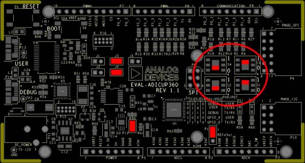
- To program the base board, set the jumpers/switches as shown in the next figure. The important jumpers/switches are highlighted in red.
- Connect the EVAL-CN0397-ARDZ to the Arduino connectors P2, P5, P6, P7, P8 of the EVAL-ADICUP360 board.
- Configure the Chip select jumper (P1) on the EVAL-CN0397-ARDZ to the 1-2 position.
- Plug in the USB cable from the PC to the EVAL-ADICUP360 base board via the Debug USB.(P14)

Obtaining the source code
We recommend not opening the project directly, but rather import it into CCES and make a local copy in your workspace.
The source code and include files of the ADuCM360_demo_cn0397 can be found on Github:
CrossCore Embedded Studio Application Source Code:
AduCM360_demo_cn0397 at Github
For more information on importing, debugging, or other tools related questions, please see the tools user guide.
Configuring the Software Parameters
- Terminal refresh - DISPLAY_REFRESH parameter - how often to refresh the output data - input time value in [msec] (CN0391.h).
- System offset calibration - USE_CALIBRATION parameter - enable/disable system offset calibration on all 3 channels - YES → enable calibration; NO → disable calibration(CN0398.h).
Outputting Data
Serial Terminal Output
- In order to view the data, you must flash the program to the EVAL-ADICUP360.
- Once complete you will need to switch the USB cable from the DEBUG USB (P14) to the USER USB (P13).
- Then follow the UART settings below with the serial terminal program.
Following is the UART configuration.
  Select COM Port
  Baud rate: 115200
  Data: 8 bit
  Parity: none
  Stop: 1 bit
  Flow Control: none
Calibration procedure
The CN0397 needs to be calibrated first before using it in order to achieve best performance. A system zero offset calibration needs to be run to cancel the offset for all of the channels. This can be done by covering and not allowing any light to reach the photodiodes.
If the calibration routine is enabled (check USE_CALIBRATION parameter) in a terminal window will pop up messages asking the user to cover the photodiodes one of the time so the calibration can be performed. With the photodiodes covered press <ENTER> button on the key board and the next message will prompt to cover the next photodiodes.

Once all the channels have been calibrated, the circuit is now ready for use. The output data will be available for each LED.

How to use the Tools
The official tool we promote for use with the EVAL-ADICUP360 is CrossCore Embedded Studio. For more information on downloading the tools and a quick start guide on how to use the tool basics, please check out the Tools Overview page.
Importing
For more detailed instructions on importing this application/demo example into the CrossCore Embedded Studios tools, please view our How to import existing projects into your workspace section.
Debugging
For more detailed instructions on importing this application/demo example into the CrossCore Embedded Studios tools, please view our How to configure the debug session section.
Project structure
The ADuCM360_demo_cn0397 is a C project that uses ADuCM36x C/C++ Project structure.
This project contains: system initialization part - disabling watchdog, setting system clock, enabling clock for peripherals; port configuration for ADC, SPI read/write; configuring and reading from AD7798, UART read/write functions; calibration and calculation of light information.

In the src and include folders you will find the source and header files related to CN0397 software application. The Communication.c/h files contain SPI and UART specific data, meanwhile the CN0397.c/h files contain the calculation part, the AD7798.c/h files contain ADC channels handling.
The RTE folder contains device and system related files:
- Device Folder – contains low levels drivers for ADuCM360 microcontroller.(try not to edit these files)
- system.rteconfig - Allows the user to select the peripherial components they need, along with the startup and ARM cmsis files needed for the project.
End of Document
resources/eval/user-guides/eval-adicup360/reference_designs/demo_cn0397.1610598242.txt.gz · Last modified: 14 Jan 2021 05:24 by Robin Getz