


This version is outdated by a newer approved version. This version (14 Jan 2021 05:31) was approved by Robin Getz.The Previously approved version (21 Mar 2018 16:48) is available.
This version (14 Jan 2021 05:31) was approved by Robin Getz.The Previously approved version (21 Mar 2018 16:48) is available.This is an old revision of the document!
Table of Contents
ADXL355 Accelerometer PMOD Demo
The ADuCM360_demo_adxl355_pmdz is an accelerometer demo project for the EVAL-ADICUP360 base board with the EVAL-ADXL355-PMDZ board, using the GNU ARM Eclipse Plug-ins in Eclipse environment.
General description
This project is an example for how to use EVAL-ADICUP360 board in combination with the EVAL-ADXL355-PMDZ accelerometer PMOD board.
The ADuCM360_demo_adxl355_pmdz project uses the EVAL-ADXL355-PMDZ which has the ADXL355 3-axis MEMS accelerometer on board.

The application reads the X , Y , and Z acceleration registers. The acceleration in the 3 axis is displayed in [G]. There is an internal temperature sensor in the ADXL355, which is converted by the on chip 12-bit ADC. The acceleration range can also be selected by setting the ADXL355_RANGE variable with the ADXL355.h file. (Values of [2, 4, and 8 are acceptable] )
All the outputs are printed from the UART to the USER USB port and can be read on the PC using a serial terminal program, such as Putty or Tera Term.
For precision applications, each ADXL355 chip requires individual calibration which can be done by measuring and setting the definitions ACC_TEMP_BIAS and ACC_TEMP_SENSITIVITY parameters in the ADXL362.h file.
The temperature in degrees celsius, can be derived from the ADC readings Tadc using the predefined formula:
Temp = (Tadc - ADXL355_TEMP_BIAS)/ ADXL355_TEMP_SLOPE) + 25;
Demo Requirements
The following is a list of items needed in order to replicate this demo.
- Hardware
- EVAL-ADICUP360
- EVAL-ADXL355-PMDZ
- Mirco USB to USB cable
- PC or Laptop with a USB port
- Software
- ADuCM360_demo_adxl355_pmdz software
- CrossCore Embedded Studio (2.7.0 or higher)
- ADuCM36x DFP (1.0.2 or higher)
- CMSIS ARM Pack (4.3.0 or higher)
- Serial Terminal Program
- Such as Putty or Tera Term
Setting up the hardware
- To program the base board, set the jumpers/switches as shown in the next figure. The important jumpers/switches are highlighted in red.
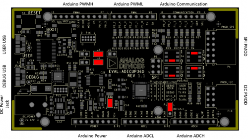
- Plug the EVAL-ADXL355-PMDZ board in the EVAL-ADICUP360 base board, via the PMOD_SPI port (P4).
- Plug in the USB cable from the PC to the EVAL-ADICUP360 base board via the User USB.(P13)

Obtaining the source code
We recommend not opening the project directly, but rather import it into CCES and make a local copy in your workspace.
The source code and include files of the ADuCM360_demo_adxl355_pmdz can be found on Github:
CrossCore Embedded Studio Application Source Code:
AduCM360_demo_adxl355_pmdz at Github
For more information on importing, debugging, or other tools related questions, please see the tools user guide.
Configuring the Software Parameters
- Temperature sensor calibration values- ADXL355_TEMP_BIAS and ADXL355_TEMP_SLOPE paramaters - find your values based on the calculation formula (ADXL355.h ):
#define ADXL355_TEMP_BIAS           (float)1852.0
#define ADXL355_TEMP_SLOPE          (float)-9.05
- Accelerometer range setting - ADXL_RANGE parameter - 2, 4, or 8 are acceptable values to set the [g] range for the ADXL355 (ADXL355.h).
#define ADXL_SENSE 2
- Sensor activity and inactivity thresholds - ACT_VALUE and INACT_VALUE paramaters used to determine at which acceleration values the sensor can react at sleep/wake-up commands (ADXL355.h):
#define ACT_VALUE          50
#define INACT_VALUE        50
- Sensor activity and inactivity time - ACT_TIMER and INACT_TIMER paramaters used to determine sleep/wake-up intervals(ADXL355.h):
#define ACT_TIMER          50
#define INACT_TIMER        50
Outputting Data
Serial Terminal Output
- In order to view the data, you must flash the program to the EVAL-ADICUP360.
- Once complete you will need to switch the USB cable from the DEBUG USB (P14) to the USER USB (P13).
- Then follow the UART settings below with the serial terminal program.
Following is the UART configuration.
  Select COM Port
  Baud rate: 9600
  Data: 8 bit
  Parity: none
  Stop: 1 bit
  Flow Control: none
The user must press the <ENTER> key each time they want to display the results.
How to use the Tools
The official tool we promote for use with the EVAL-ADICUP360 is CrossCore Embedded Studio. For more information on downloading the tools and a quick start guide on how to use the tool basics, please check out the Tools Overview page.
Importing
For more detailed instructions on importing this application/demo example into the CrossCore Embedded Studios tools, please view our How to import existing projects into your workspace section.
Debugging
For more detailed instructions on importing this application/demo example into the CrossCore Embedded Studios tools, please view our How to configure the debug session section.
Project structure
The ADuCM360_demo_adxl355_pmdz project use basic ARM Cortex-M C/C++ Project structure.
This project contains: system initialization part - disabling watchdog, setting system clock, enabling clock for peripheral; port configuration for SPI0, accelerometer sensor use; SPI read/write functions; sensor monitoring.

In the src and include folders you will find the source and header files related to ADXL355 application. You can modify as you wanted those files. The Communication.c/h files contain SPI and UART specific data, meanwhile the ADXL355.c/h files contain the accelerometer data. Here are parameters you can configure:
The RTE folder contains device and system related files:
- Device Folder – contains low levels drivers for ADuCM360 microcontroller.(try not to edit these files)
- system.rteconfig - Allows the user to select the peripherial components they need, along with the startup and ARM cmsis files needed for the project.
End of Document
resources/eval/user-guides/eval-adicup360/reference_designs/demo_adxl355.1610598236.txt.gz · Last modified: 14 Jan 2021 05:23 by Robin Getz