


This version is outdated by a newer approved version. This version (18 Aug 2021 16:51) was approved by Brandon Bushey.The Previously approved version (23 Apr 2021 17:47) is available.
This version (18 Aug 2021 16:51) was approved by Brandon Bushey.The Previously approved version (23 Apr 2021 17:47) is available.This is an old revision of the document!
Table of Contents
Smart Greenhouse Demo
The Smart Greenhouse is a WI-FI cloud enabled or local serial terminal application for the EVAL-ADICUP3029 base board with additional Soil shield EVAL-CN0398-ARDZ, Light shield EVAL-CN0397-ARDZ, LED shield EVAL-CN0410-ARDZ created with Analog Devices Cross Core Embedded Studio.
General Description/Overview
The Smart Greenhouse project uses the soil shield EVAL-CN0398-ARDZ to collect data about temperature, moisture and pH, the EVAL-CN0397-ARDZ to get information about light intensity and concentration for red, blue and green light and the EVAL-CN0410-ARDZ to control a led array to get the desired light intensity.
The EVAL-ADICUP3029 is designed for IOT (Internet of Things) applications in mind, and therefore comes with on board Wi-Fi ESP8266 module.
In order to fully make use of IOT cloud connectivity, the Arrow SDK or IBM Watson is used to connect to cloud services and have and interface to receive data and send commands.
Demo Versions Supported
There are a few demo versions supported using the same algorithm and application level code. The only difference for each of these options is how you would view the data and interact with the design.
- IBM Watson Smart Greenhouse
- PC Command Line Smart Greenhouse
IBM Watson Smart Greenhouse
Demo Requirements
The following is a list of items needed in order to replicate this demo.
- Boards/Hardware
- ESP8266 Module (comes with EVAL-ADICUP3029)
- Internet connected gateway – utilize existing Wi-Fi gateway/router/mobile hotspot
- Cables/Power
- Micro USB to USB cable (comes with EVAL-ADICUP3029)
- PC or Laptop with a USB port
- Sensors/Leds
- An LED light bar (We used the CFTL-LED-BAR for our demo)
- A pH probe (We used the Atlas Scientific for our demo)
- A moisture sensor (We used the Vegetronix VH400 for our demo)
- A PT100 RTD (Any 3-wire PT100 should work)
- Software
- ADuCM3029_IBMWatson_Greenhouse software
- CrossCore Embedded Studio (2.6.0 or higher)
- ADuCM302x DFP (2.0.0 or higher)
- ADICUP3029 BSP (1.0.0 or higher)
- IBM Watson Account
Setting up the Hardware
- Move the S2 switch to the WiFi position on the EVAL-ADICUP3029.

- The ESP8266 Enable Pin needs to be tied directly to 3.3V or pulled high to the GPIO via a 10K ohm resistor. Because this is not currently on the Rev B or Rev C version of the ADICUP3029, you will need to solder a small fly wire from the 3.3V pin to the enable pin.
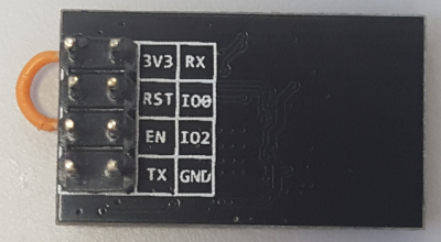

- Plug the ESP8266 in the P1 connector on the EVAL-ADICUP3029.
- Configure the EVAL-CN0398-ARDZ CS option by setting the pin jumper of P5 to pin 1 and 2. Set P8 moisture power supply to 3V3 and VIN Supply to 5V.
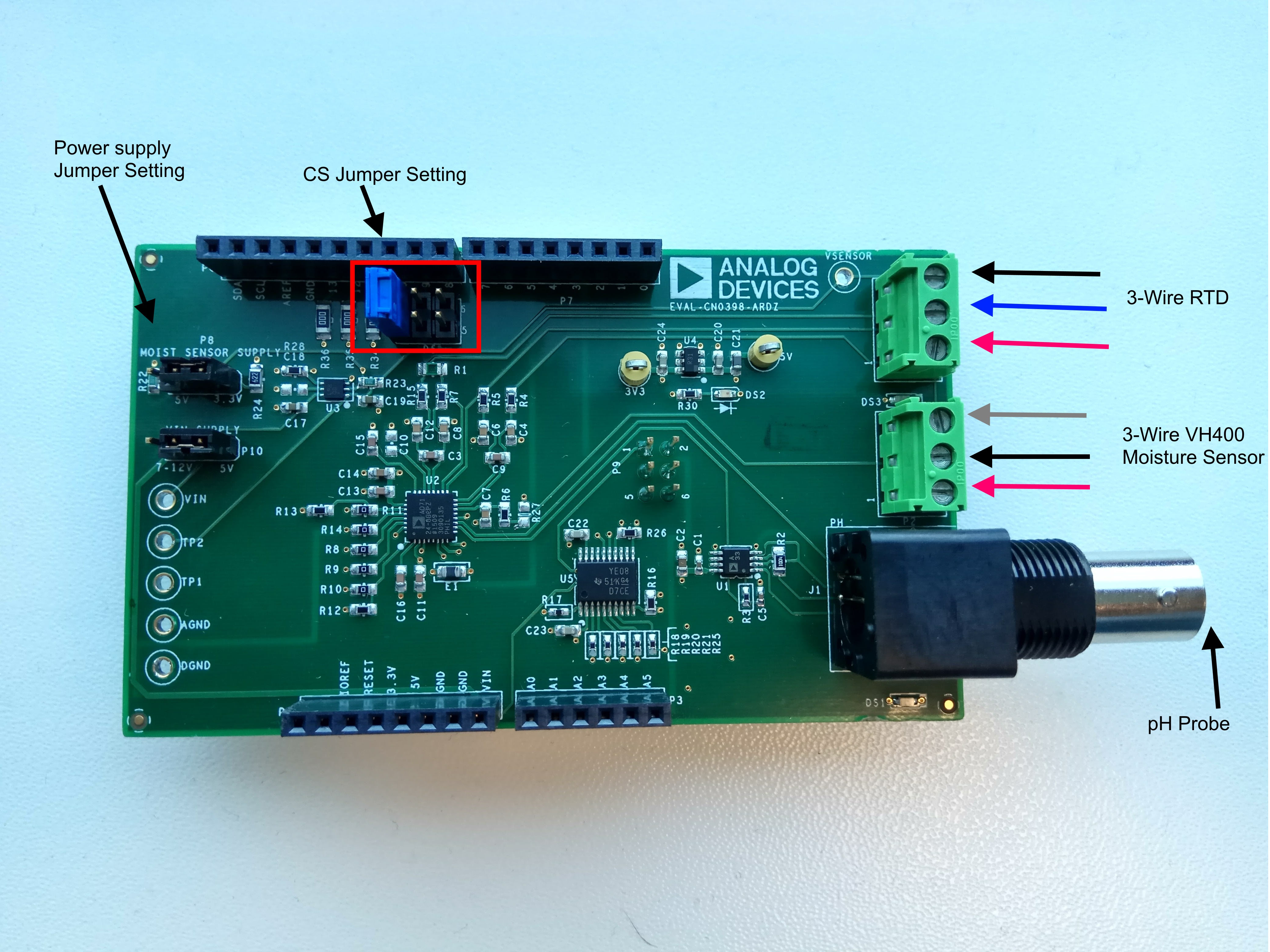
- Configure CS jumper for CN0397 to pins 3 and 4.

- Configure CS jumper on P21 for CN0410 to pins 1 and 2. An external power supply must be used to power the board and the jumper on P20 must be set to 1 and 2.

- The Led Bar must be connected to the CN0410 board to enable power to the leds. Also to select the leds we want to controll we have to place the jumpers to pins 1 and 2. In this picture only RLED1, GLED1 and BLED1 are selected.


IBM Watson Smart Greenhouse Source Code
There are two basic ways to program the ADICUP3029 with the software for the IBM Watson Smart Greenhouse.
- Dragging and Dropping the .Hex to the Daplink drive
- Building, Compiling, and Debugging using CCES
Using the drag and drop method, the software is going to be a version that Analog Devices creates for testing and evaluation purposes. This is the EASIEST way to get started with the reference design
Importing the project into CrossCore is going to allow you to change parameters and customize the software to fit your needs, but will be a bit more advanced and will require you to download the CrossCore toolchain.
The software for the ADuCM3029_IBMWatson_Greenhouse can be found here:
Prebuilt IBM Watson Greenhouse Hex File
Complete IBM Watson Greenhouse Source Files
Configuring Software for IBM Watson Greenhouse
This section will describe the steps needed to get the IBM Watson Greenhouse up and running.
Creating an IBM Watson account
The first step is to get an IBM account for IoT projects. Acces this link https://www.ibm.com/cloud/#/ibmssolanding and click Sign Up.

After login you will arrive at the dashboard page.

Choose to create a resource and select the Internet of Things platform.

Give the resource a Service name and create it. After this the last step is to launch the resource.

Create a device
The next now is to create a device inside IBM Watson in order to recognize our physical device. Click on the Devices option from the side tab.

To add the device please follow this tutorial https://developer.ibm.com/recipes/tutorials/how-to-register-devices-in-ibm-iot-foundation/
Setting WIFI connection
In order to establish the connection to the WIFI we have to set the aWifiSSID and aWifiPassword to connect to the access point (wifi router). This is done modifying ADuCM3029_IBMWatson.h.

Establishing the connection
The last step is to connect our device to the IBM platform. There still are few fields in ADuCM3029_IBMWatson.h that need to be completed.
First let's set the MQTT username and password. The username is always use-token-auth. For the password use the Authentication token when you created the device in the tutorial above.

The last step is to set the MQTT configuration. The broker ip is the same as you IBM Watson IoT platform link. it should be something similar to this 0qqrd7.internetofthings.ibmcloud.com where 0qqrd7 is the Organization ID. Replace the address from ADuCM3029_IBMWatson.h, aMQTTBrokerIp with your own. The port is always 1883.
The publisher name is composed of d:OrganizationID:ClientName:DeviceName in the end you end up with something like d:0qqrd7:C_Client:ADI_GreenHouse.
The final thing to do is set the Topic name and the Subscribe Topic. We will need the subscribe topic to send commands to the device from an application. An example is to create a NodeRed application and connect it to the cloud. This will enable us to send commands to the device. But first lets set those two things we mentioned earlier.
- Compose the Topic name: iot-2/evt/DeviceID/fmt/json in our case we have d:0qqed7:C_Client:ADI_GreenHouse
- Compose Subscribe topic: iot-2/cmd/DeviceID/fmt/json this is you subscribe topic iot-2/cmd/ADI_GreenHouse_cmd/fmt/json
For an application creation you will need to create a Node Red starter pack inside IBM following this link https://console.bluemix.net/catalog/starters/node-red-starter
 Click on visit App URL then just go to Node Red Editor. This is an application example using Node Red dashboard pack.
  For more documentation on NodeRed just visit https://nodered.org/ and follow the documentation.
IBM Watson Smart Greenhouse Software Flow/Diagram

The greenhouse application involves 4 layers:
- Hardware, arduino shields layer
- Communication layer (SPI communication)
- Processing layer (ADICUP3029 and ESP8266)
- Cloud layer
The hardware part is composed of the shields stacked on top of each other, which provide data from the sensors and also control the leds. For more details about these CNs you can consult the individual page for each one:
The communication layer configures the shields and is responsible for transferring information from and to the desired device. Data is then available for processing and transmitting to the cloud.
ADICUP3029 ensures the logic for the localized operations while the ESP8266 establishes the connection to the cloud and send the data over WIFI.
Output Data
Data from the device can be visualized inside the IBM Watson IoT platform. Just navigate to devices and click on the one you created.

Also can be visualized in nodeRed with the dashboard pack. This will create a more visual way is displaying data.

For nodered documentation follow https://nodered.org/.
Serial Terminal Smart Greenhouse
Demo Requirements
The following is a list of items needed in order to replicate this demo.
- Boards/Hardware
- EVAL-ADICUP3029
- EVAL-CN0397-ARDZ
- EVAL-CN0398-ARDZ
- EVAL-CN0410-ARDZ
- ESP8266 Module
- Internet connected gateway – utilize existing Wi-Fi gateway/router/mobile hotspot
- Cables/Power
- Micro USB to USB cable
- PC or Laptop with a USB port
- Sensors/Leds
- An LED light bar (We used the CFTL-LED-BAR for our demo)
- A pH probe (We used the Atlas Scientific for our demo)
- A moisture sensor (We used the Vegetronix VH400 for our demo)
- A PT100 RTD (Any 3-wire PT100 should work)
- Software
- ADuCM3029_Local_Greenhouse software
- CrossCore Embedded Studio (2.6.0 or higher)
- ADuCM302x DFP (2.0.0 or higher)
- ADICUP3029 BSP (1.0.0 or higher)
- Putty or Tera Term or other serial terminal program
Setting up the Hardware
- Move the S2 switch to the USB position on the EVAL-ADICUP3029.
- Configure the EVAL-CN0398-ARDZ CS option by setting the pin jumper of P5 to pin 1 and 2. Set P8 moisture power supply to 3V3 and VIN Supply to 5V.
- Configure CS jumper for CN0397 to pins 3 and 4.
- Configure CS jumper on P21 for CN0410 to pins 1 and 2. An external power supply must be used to power the board and the jumper on P20 must be set to 1 and 2.
- The Led Bar must be connected to the CN0410 board to enable power to the leds. Also to select the leds we want to control we have to place the jumpers to pins 1 and 2. In this picture only RLED1, GLED1 and BLED1 are selected.
Serial Terminal Smart Greenhouse Source Code
There are two basic ways to program the ADICUP3029 with the software for the Serial Terminal Smart Greenhouse.
- Dragging and Dropping the .Hex to the Daplink drive
- Building, Compiling, and Debugging using CCES
Using the drag and drop method, the software is going to be a version that Analog Devices creates for testing and evaluation purposes. This is the EASIEST way to get started with the reference design
Importing the project into CrossCore is going to allow you to change parameters and customize the software to fit your needs, but will be a bit more advanced and will require you to download the CrossCore toolchain.
The software for the ADuCM3029_Local_Greenhouse can be found here:
Prebuilt Local Greenhouse Hex File
Complete Local Greenhouse Source Files
Configuring Serial Terminal Software for Smart Greenhouse
The serial greenhouse project is a local deployed solution. It does not use WIFI connection and all communication is done over UART.
Serial terminal Greenhouse Software Flow/Diagram

The greenhouse application involves 3 layers:
- Hardware, Arduino shields layer
- Communication layer (SPI communication)
- Processing layer (ADICUP3029 and ESP8266)
The hardware part is composed of the shields stacked on top of each other, which provide data from the sensors and also control the leds. For more details about these CNs you can consult the individual page for each one:
The communication layer configures the shields and is responsible for transferring information from and to the desired device. Data is then available for processing and transmitting to the cloud.
ADICUP3029 ensures the logic for all the operations and once the data is available, it is being sent over UART and made available for the user. The user can also send commands to the device to control the leds intensity.
Output Data
Data is represented in json format and sent over UART. Use a Putty service set to 9600 baud rate.

After sending a command we can read again the values of the sensors to see the intensity change.

How to use the Tools
The official tool we promote for use with the EVAL-ADICUP3029 is CrossCore Embedded Studio. For more information on downloading the tools and a quick start guide on how to use the tool basics, please check out the Tools Overview page.
Importing
For more detailed instructions on importing this application/demo example into the CrossCore Embedded Studios tools, please view our How to import existing projects into your workspace section.
Debugging
For more detailed instructions on importing this application/demo example into the CrossCore Embedded Studios tools, please view our How to configure the debug session section.
End of Document
resources/eval/user-guides/eval-adicup3029/reference_designs/smart_greenhouse.1629298305.txt.gz · Last modified: 18 Aug 2021 16:51 by Brandon Bushey