


This version is outdated by a newer approved version. This version (21 Apr 2020 08:37) is a draft.
Approvals: 0/1
This version (21 Apr 2020 08:37) is a draft.Approvals: 0/1
This is an old revision of the document!
Table of Contents
THIS IS A TEMPLATE.
THE GOAL IS TO CREATE A DOCUMENT CUSTOMERS WILL USE WHEN SETTING UP THEIR CFTL DEMO, SO THEY DON'T ASK YOU SO MANY QUESTIONS. IT'S DESIGNED TO HELP YOU GET STARTED WRITING YOUR REFERENCE DEMO USER GUIDE.
ALL OF THE CONTENT IS PLACEHOLDER INFORMATION, SO YOU WILL NEED TO POPULATE RELEVANT INFORMATION TO YOUR CFTL. SOME(OR SEVERAL) OF THE SECTION HEADERS MAY NOT APPLY TO YOU, SIMPLY REMOVE THEM. ALSO I MAY NOT HAVE CAPTURED EVERYTHING RELATIVE TO YOUR BOARD, SO ADDING INFORMATION IS ACCEPTABLE.
DON'T FORGET TO CREATE A MEDIA FOLDER SPECIFIC TO YOUR DEMO FOR ANY IMAGES, FILES, OR DOCUMENTS YOU WISH TO INCLUDE. THIS WILL HELP US KEEP THE WIKI ORGANIZED AND ENSURE YOUR CONTENT DOESN'T GET REMOVED.
Optical Platform Demo (w/ EVAL-CN0503-ADRZ)
The ADuCM3029_demo_cn0503 project provides a solution to get multiple liquid parameters (for example turbidity, pH, fluorescence, etc.) using the EVAL-CN0503-ARDZ and the EVAL-ADICUP3029. It uses a a complete multimodal sensor front end, stimulating up to eight LEDs and measuring the return signal on up to eight separate current inputs using photo-diodes. The board is controlled via a command line interface (CLI), Python scripts that provide high level functions or a Python GUI that communicates with the firmware via serial terminal.
General Description/Overview
The ADuCM_demo_cn0503 project uses EVAL-CN0503-ARDZ to provide a method to determine properties of liquids, for example turbidity, fluorescence and pH. To do this the application must configure the ADPD4101 sensor, read the data from it and perform calculations on the data to improve SNR and pre-processes it to units as close to the desired measurement as possible.
The application configures the device to stimulate LEDs and read the PDs in 4 time slots, each corresponding to one of the optical paths present on the board. It enables 2 ADC channels per time slot to measure the light beam before and after passing through the substance. This means that a packet of 8 samples of data come from the ADC once per sampling period.
 add diagram
The samples can then be plugged into a user defined equation that can include any of the samples and any random constant to generate a ratio, which the application defines as the 'absolute ratio'. Before being displayed or used any further the absolute ratio is filtered by a block average filter and a rolling average filter to digitally increase the SNR and take out unwanted frequencies. The bandwidth of the rolling average filter can be set by the user. After getting the absolute ratio that describes the liquid that is now in the vat, it can be used to compare it to the baseline measurement using either 1 - (absolute ratio / baseline) or (absolute ratio / baseline) equations. The user has to input the baseline for each optical path as well as the equation from these options. The application defines this result as the 'relative ratio'. The application then has 2 more options of processing the information in the form of two 5th order polynomials in which the relative ratio can be inserted as the variable. The coefficients of each of the polynomial members are also input by the user via the CLI. To be noted that the result of the first equation is the variable for the second equation. This gives the user a high degree of flexibility in getting data out of the platform.
Demo Requirements
The following is a list of items needed in order to replicate this demo.
- Hardware
- EVAL-ADICUP3029
- EVAL-CN0503-ARDZ
- Mirco USB to USB cable
- PC or Laptop with a USB port
- 3D printed mechanical fixtures described in the Hardware User Guide
- Software
- CrossCore Embedded Studio (2.8.0 or higher)
- ADuCM302x DFP (3.2.0 or higher)
- ADICUP3029 BSP (1.1.0 or higher)
- Serial Terminal Program
- Such as Putty or Tera Term
Setting up the Hardware
- Set up the the EVAL-CN0503-ARDZ as shown in the Hardware User Guide.
- Connect the board to the EVAL-ADICUP3029 via the Arduino headers. add picture
- Connect a micro-USB cable to P10 connector of the EVAL-ADICUP3029 and connect it to a computer. The final setup should look similar to the picture below. add picture
Configuring the Software
The ADuCM3029_demo_cn0503 does not need any software configuration. It can be built and run as is.
Outputting Data
A serial terminal is an application that runs on a PC or laptop that is used to display data and interact with a connected device (including many of the Circuits from the Lab reference designs). The device's UART peripheral is most often connected to a UART to USB interface IC, which appears as a traditional COM port on the host PC/ laptop. (Traditionally, the device's UART port would have been connected to an RS-232 line driver / receiver and connected to the PC via a 9-pin or 25-pin serial port.) There are many open-source applications, and while there are many choices, typically we use one of the following:
Before continuing, please make sure you download and install one of the above programs.
There are several parameters on all serial terminal programs that must be setup properly in order for the PC and the connected device to communicate. Below are the common settings that must match on both the PC side and the connected UART device.
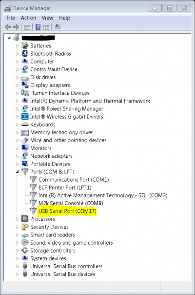
- COM Port - This is the physical connection made to your PC or Laptop, typically made through a USB cable but can be any serial communications cable. You can determine the COM port assigned to your device by visiting the device manager on your computer. Another method for identifying which COM port is associated with a USB-based device is to look at which COM ports are present before plugging in your device, then plug in your device, and look for a new COM port.
- Baud Rate - This is the speed at which data is being transferred from the connected device to your PC. These parameters must be the same on both devices or data will be corrupted. The default setting for most of the reference designs in 115200.
- Data Bits - The number of data bits per transfer. Typically UART transmits ASCII codes back to the serial port so by default this is almost always set to 8-Bits.
- Stop Bits - The number of “stop” conditions per transmission. This usually set to 1, but can be set to 2 for redundancy.
- Parity - Is a way to check for errors during the UART transmission. Unless otherwise specified, set parity to “none”.
- Flow Control - Is a way to ensure that data lose between fast and slow devices on the same UART bus are not lost during transmission. This is typically not implemented in a simple system, and unless otherwise specified, set to “none”.
In many instances there are other options that each of the different serial terminal applications provide, such as local line echo or local line editing, and features like this can be turned on or off depending on your preferences. This setup guide will not go over all the options of each tool, but just the minor features that will make it easier to read back data from the connected devices.
Example setup using Putty
- Plug in your connected device using a USB cable or other serial cable.
- Wait for the device driver of the connected device to install on your PC or Laptop.
- Open your device manager, and find out which COM port was assigned to your device.
- Open up your serial terminal program (Putty for this example)
- Click on the serial configuration tab or window, and input the settings to match the requirements of your connected device. The default baud rate for most of the reference designs is 115200. Make sure that you use the correct baud rate for your application.
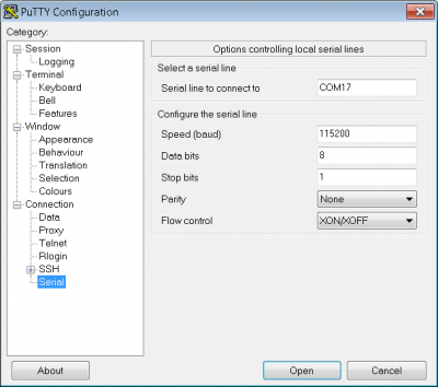
- Ensure you click on the checkboxes for Implicit CR in every LF and Implicit LF in every CF.
- Ensure that local echo and line editing are enabled, so that you can see what you type and are able to correct mistakes. (Some devices may echo typed characters - if so, you will see each typed character twice. If this happens, turn off local echo.)

- Click on the open button, and as long as your connected device and serial terminal program are setup the same, than you should see data displaying.


Hint: If you see nothing in the serial terminal, try hitting the reset button on the embedded development board.
Available commands
Typing help or h after initial calibration sequence will display the list of commands and their short versions. Bellow is the short command list:
| Function | Command | Description | Example |
|---|---|---|---|
| General commands | |||
| h | Display available commands. | ||
| stts | Display parameters of the application. | ||
| Internal register commands | |||
| r | Display voltage or current on the selected channel. <chan> = channel to be shown | ||
| sur | Change channel update rate. <rate> = new channel update rate in Hz. If it is bigger than output data rate divided by 80 can cause unpredictable behaviour. | ||
| HART commands | |||
| he | Enable HART channel. | ||
| hd | Disable HART channel. | ||
| hcc | Select wanted channel. <chan> = Channel to be selected. | ||
| ht | Transmit string through HART. <string> = string to be transmitted. | ||
| hg | Send the received buffer through UART connection. | ||
| hcz | Send command zero with the specified number of FFs in the preambule. <pbsize> = size of the preambule (no. of 0xFFs in the beginning). | ||
| hpt | Send command zero with the specified number of FFs in the preambule. <byte> = byte to send in loop. | ||
| ADC commands | |||
| arr | Display value of ADC register of the given address. <reg> = address of the register. | ||
| awr | Change value of the ADC register of the given address. <reg> = address of the register. <val> = new value of the register. | ||
| ags | Get a specific number of samples from the given channel. <ch> = selected chanel. <nr> = number of channels; cannot exceed 2048. | ||
| aso | Set sample rate. <sps> = selected sample rate option. If it is smaller than channel update rate multiplied by 80 can cause unpredictable behaviour. | ||
| asf | Set filter option. <filter> = selected filter option. | ||
| aep | Enable post filter. | ||
| adp | Select postfilter. <opt> = selected postfilter option. | ||
| asp | Reset controller, parameters and faults | ||
| aowe | Enable open wire detection. | ||
| aowd | Disable open wire detection. | ||
| EEPROM commands | |||
| de | Discover EEPROM I2C addresses if there are any. |

Obtaining the Source Code
We recommend not opening the project directly, but rather import it into CrossCore Embedded Studios and make a local copy in your workspace.
The source code and include files of the ADuCM3029_demo_cn0414 can be found here:
How to use the Tools
The official tool we promote for use with the EVAL-ADICUP3029 is CrossCore Embedded Studio. For more information on downloading the tools and a quick start guide on how to use the tool basics, please check out the Tools Overview page.
Importing
For more detailed instructions on importing this application/demo example into the CrossCore Embedded Studios tools, please view our How to import existing projects into your workspace section.
Debugging
For more detailed instructions on importing this application/demo example into the CrossCore Embedded Studios tools, please view our How to configure the debug session section.
Project Structure
The program is composed of two main parts:
- Board setup with initial values.
- Main process.

Board setup initializes UART, SPI and I2C communication and verifies if there is an active EVAL-CN0414-ARDZ board connected by reading the AD4111 ID register. Here is also initialized the update timer for the internal channel registers.

The main process routine implements the CLI and calls the commands input by the user. This routine also checks the flags asserted in the asynchronous events (the update channel register flag, the HART received flag and the floating channel flags) and calls the appropriate handler methods. There is also a flag asserted by the channel register update rate and the ADC output data rate. If the update rate would be too close to the output data rate, the actual update rate might slow down to be possible for the program to maintain all functionality. The update rate may never be bigger or equal to the ADC output data rate divided by 8 (for 8 channels).

The flow chart below represents the way the channel registers are updated. Only one channel is active at any one time (the channel that must be read).

End of Document
resources/eval/user-guides/eval-adicup3029/reference_designs/demo_cn0503.1587451033.txt.gz · Last modified: 21 Apr 2020 08:37 by Andrei Drimbarean