This version is outdated by a newer approved version. This version (10 Aug 2018 10:20) is a draft.
Approvals: 0/1
This is an old revision of the document!
EVAL-AD8302-ARDZ

The EVAL-AD8302-ARDZ shield illustrates the functionality of the AD8302, a gain and phase detector which operates from low frequency up to 2.7 GHz. The voltage outputs of the AD8302 are routed to the ANALOG IN connector of the Arduino base board. This allows the RF power detector’s output voltage to be easily digitized and processed by the Arduino base board’s integrated six-channel ADC.
The power supply for the board comes from the Arduino base board through the POWER connector (5V). So there is no need to connect an external power supply.
The EVAL-AD8302-ARDZ was designed to work with EVAL-ADICUP3029 and Linduino. For both platforms, a PC software GUI and device drivers are available.
Shield Specifications
Setting Up the Hardware
Software GUI for ADICUP3029
Software Installation
Download the Software
GUI file
here.
Extract the Software
GUI file to your computer.
Connect the Eval-ADICUP3029 board using micro
USB cable.
Set the S2 switch to
USB.

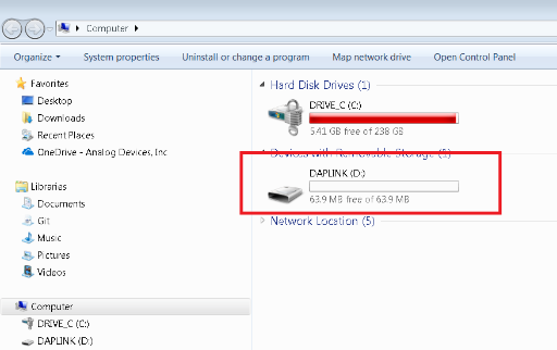
In the extracted files look for “power_detector-firmware.hex” then copy the hex file to Computer»DAPLINK drive

After loading the hex file to the DAPLINK drive the window explorer must automatically close or else you need to load the hex file to the drive again.
After the windows explorer automatically closes, reset the Eval-ADICUP3029 board by pressing the S1 (reset) button on the board.
Go to extracted files and look for “power_detector.exe” file and double click to run the software. The Connection Window will open.

Software Operation
Connection Window
-
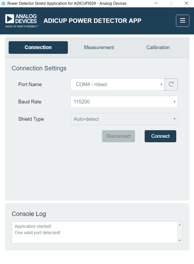
Click the refresh button on Port Name to Identify the port where an ADICUP3029 is installed

If there are many ADICUP3029 installed, select the port where ADICUP3029 and EVAL-AD8302-ARDZ connected
Set Baudrate to 115200
Select Auto-detect on Shield type.
Click Connect. The Measurement Window should Open.
Console Log must indicate “AD8302shield detected with ADiCUP”
Measurement Window

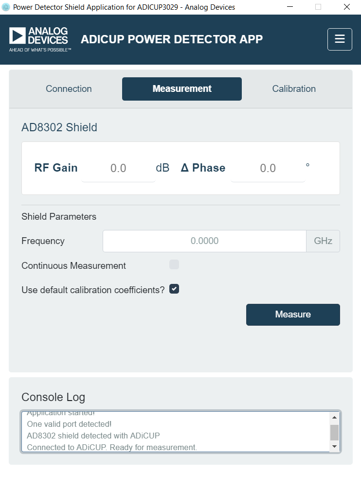
The shield measures Gain and Phase Difference based on a 2-point calibrated linear response characterized for a specific frequency. By using default calibration coefficients, the 2-point linear response corresponds to the datasheet specifications of AD8302. By using the user calibration coefficients, the frequency dependent 2-point linear response corresponds to the calibration made by the user.
The user calibration coefficients and default calibration coefficients are INITIALLY the same. Therefore any unchanged calibration at specific frequencies in the user calibration coefficients retains the default values
Related topic: Calibration of EVAL-AD8302-ARDZ
Select Calibration Coefficients:
To make single measurement:
Enter the frequency of the input RF signal
Uncheck Continuous Measurement
Click Measure Button
Not entering the correct frequency may result to less accurate measurements.
To continuously make measurements:
Enter the frequency of the input RF signal
Check Continuous Measurement
Click Measure Button
Click Stop to stop measuring at the last measurement
Not entering the correct frequency may result to less accurate measurements.
To switch windows:
Click “Connection” or “Calibration” to switch to respective window.
Calibration Window

Select the frequency
Input to J1 an RF signal of-20dBm
Input to J2 an RF signal of-40dBm
Click “Measure”
Input to J1 an RF signal of-40dBm
Input to J2 an RF signal of-20dBm
Click “Measure”
Click “Calibrate”

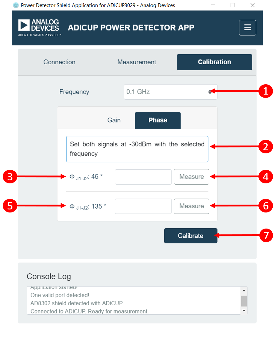
Select frequency
Set the signal power of inputs to -30dBm
Set phase between inputs to be 45º
Click measure
Set phase between inputs to be 135º
Click measure
Click “Calibrate”
User must be able to synchronize the phase of input signals perhaps, by using external devices/equipment, to do this calibration
If desired frequency of calibration or measurement is not on the list, calibrate on the immediate higher frequency available and on the immediate lower frequency available. If desired frequency is higher/lower than the available frequency selection, calibrate only on the highest/lowest frequency selection
Development on ADICUP3029
Software GUI for Linduino
Software Installation
Software Operation
Development on Linduino
 This version (10 Aug 2018 10:20) is a draft.