


This version (14 Jan 2021 05:33) was approved by Robin Getz.The Previously approved version (03 Jan 2021 21:46) is available.
Table of Contents
EV-COG-AD3029WZ MCU Cog
The EV-COG-AD3029WZ is an MCU Cog board for the ADuCM3029 MCU.
Main Features
- ADuCM3029 (WLCSP package) - Ultra Low Power ARM Cortex-M3 MCU
- Compact form factor (3.5 cm X 7.5 cm) - Easy to deploy.
- On board debugger capability (CMSIS DAP compatible)
- Multiple power options and current monitoring test-points.
- On-board sensors: Accelerometer (ADXL362) and Temperature Sensor (ADT7420)
- Optional expansion capability - Using application specific add-on cards (Gears)
- Optional connectivity options - Using RF modules (Connectivity Cogs)
Board
Front-Side
this image needs to be changed

Back-Side
this image needs to be changed

Power
The MCU Cog board offers flexibility in terms of power supply and power muxing options. This is achieved with the use of jumpers on the board. The Cog board also offers multiple test points for monitoring current consumption.
Power Supply Options
The MCU Cog offers the following power supply options:
- 5V USB power (USB microB connector)
- 3V CR2032 Coin cell (Cell holder - BT1)
- 3V - 6V Rechargeable Li-Ion Battery (JST Connector - P6)
- 3V - 6V External Supply from an MCU Cog Add-on card (via Connector C1)
Power Muxing Options
For details of the power muxing scheme, refer to the figure below.

Do not insert shunt b/w positions 5 & 6 of JH4 when using USB supply. Doing so can permanently damage this board.
Refer to the Jumper Settings section further below for details on power related jumpers on the board
Power Regulator
The MCU Cog board uses an on-board switching regulator - the ADP5300, which is a high efficiency, ultra-low power step down regulator. The MCU has complete control over the switching modes of the regulator via GPIO. The pin-mapping is shown in the table below.

Current Measurement Options
The MCU Cog enables IOT developers to measure and profile current consumption at different places on the board to enable isolation of current consumption hotspots. The current measure test points shown in the table below can be used along with a digital multimeter to profile current consumption.

Programming & Debug Options
The MCU Cog offers the following debug options:
- On-board CMSIS-DAP debugger (USB microB connector)
- JLINK-9 Connector for access to SWD interface (P26)
- Access to SW interface to an MCU Cog Add-on card (via Connector C2)
Wireless Connectivity Options
The MCU Cog board offers support for ADI RF daughter-cards such as the EV-ADF70301-915AZ via the “EV-COG-BLEINTP1” connectivity Cog board that can be attached at Connector P2. This connectivity Cog board also has on-board BTLE circuit enabling the MCU Cog board to use BTLE communication as well. More details regarding wireless connectivity options are available on the EV-COG-BLEINTP1 Wiki page.
Buttons/LED(s)
The MCU Cog offers 2 buttons and 2 LED(s) that can be used by the Application. The default GPIO connections are shown in the tables below.

Expansion Connectors
One of the USP of the MCU Cog is access to ALL GPIO via Expansion Connectors (“C1” and “C2”) for an Add-on card to utilize in its Application. This enables developers to confidently build final form factor hardware without having to worry about porting their firmware. The figures below capture the pin-mapping and jumpers that need to be changed to get external access (via the expansion connectors) to GPIO (as well as power/reset, etc).
Expansion connector "C1"


Expansion connector "C2"


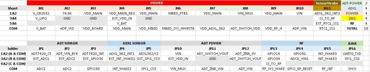
Jumper Settings
The MCU Cog offers flexibility in terms of power muxing options and the facility to route any GPIO externally via the expansion connectors “C1” and “C2”. This is achieved with the use of jumpers. The MCU Cog has two types of jumpers - those labelled “JHx” and which are 2×2 1.27mm pitch headers and those labelled “JPx” and which are solder jumpers. The “JHx” jumpers are expected to be used more frequently than the “JPx” jumpers. The figures below capture the jumper settings.


Jumper locations on board
The following image of the bottom layer of the PCB highlights the jumper positions on the board:

Note that the jumpers JH6 and JP16 on the top layer of the board.
Changing the jumper settings
Shunt Jumpers (JHx)
As mentioned above, the shunt jumpers are 1.27mm headers, whose pins are shorted using a shunt. This shunt is inserted by default in the positions as mentioned in the table above.
To change a jumper setting, carefully remove the shunt from its position, and re-insert the shunt in the correct position corresponding to the pin numbers to be shorted. The pin numbers are mentioned on the silkscreen of the PCB (usually both pin 1 & 2) and thus the default positions can be located.
For example JH11 controls which signal is sent to the RTC1_SS2 SensorStrobe pin. By default the ADXL_362_INT2 signal is connected to the SensorStrobe pin. In order to connect the RF module, JH11 needs to be moved from “1 and 2” to “3 and 4”. The corresponding change is shown below:

Solder Jumpers (JPx)
Solder jumpers are shorted using a solder blob. There are 16 such jumpers on the board, out of which 15 are on the bottom side of the board while 1 (JP16) is on the top side of the board. Positions 1, 2 and 3 are usually indicated along the jumpers.
To change a solder jumper, using a hot soldering iron, melt the blob of solder and move it into the desired position (1-2 or 3-2 or 4-2).
For example, GPIO30 is connected to the on board ADT7420 temperature sensor by default. In order to bring it out to the expander JP3 needs to be shifted from 1-2 to 2-3. After using a soldering iron to shift the jumpers, this is how it looks before and after:

MCU Cog Design and Integration Files
Add-on Template
For developers designing a Cog add-on board, the template schematic/board files below might be a useful starting point. The board file has the placement of the expansion connectors as well as place-bound rules embedded.
End Document
resources/eval/user-guides/ev-cog-ad3029wz/cog_hw_userguide.txt · Last modified: 14 Jan 2021 05:24 by Robin Getz