


This version is outdated by a newer approved version. This version (25 Apr 2016 21:58) is a draft.
Approvals: 0/1
This version (25 Apr 2016 21:58) is a draft.Approvals: 0/1
This is an old revision of the document!
Table of Contents
PulSAR ADC PMODs
These low power ADCs offer very high performance from 14-bits up to 18-bits with throughputs ranging from 100ksps to 1.3MSPS. The boards are designed to demonstrate the ADC's performance and to provide an easy digital interface for a variety of system applications. A full description of these products are available in their respective data sheets and should be consulted when utilizing the boards.

The products which have PMOD boards associated with them can be found in the table below.
| Products | Resolution | Throughput | Input Stage | Driver Amplifier | PMOD Part Number |
| AD7942 | 14-Bits | 250 KSPS | Unipolar, Single-Ended Input | ADA4841 | EVAL-AD7942-PMDZ |
| AD7946 | 14-Bits | 500 KSPS | Unipolar, Single-Ended Input | ADA4841 | EVAL-AD7946-PMDZ |
| AD7988-1 | 16-Bits | 100 KSPS | Unipolar, Differential Input | ADA4841 | EVAL-AD7988-1-PMDZ |
| AD7685 | 16-Bits | 250 KSPS | Unipolar, Single-Ended Input | ADA4841 | EVAL-AD7685-PMDZ |
| AD7687 | 16-Bits | 250 KSPS | Unipolar, Differential Input | ADA4841 | EVAL-AD7687-PMDZ |
| AD7691 | 16-Bits | 250 KSPS | Unipolar, Differential Input | ADA4841 | EVAL-AD7691-PMDZ |
| AD7686 | 16-Bits | 500 KSPS | Unipolar, Single-Ended Input | ADA4841 | EVAL-AD7686-PMDZ |
| AD7688 | 16-Bits | 500 KSPS | Unipolar, Differential Input | ADA4841 | EVAL-AD7688-PMDZ |
| AD7693 | 16-Bits | 500 KSPS | Unipolar, Differential Input | ADA4841 | EVAL-AD7693-PMDZ |
| AD7988-5 | 16-Bits | 500 KSPS | Unipolar, Single-Ended Input | ADA4841 | EVAL-AD7988-5-PMDZ |
| AD7980 | 16-Bits | 1000 KSPS | Unipolar, Single-Ended Input | ADA4841 | EVAL-AD7980-PMDZ |
| AD7983 | 16-Bits | 1333 KSPS | Unipolar, Single-Ended Input | ADA4841 | EVAL-AD7983-PMDZ |
| AD7690 | 18-Bits | 400 KSPS | Unipolar, Differential Input | ADA4841 | EVAL-AD7690-PMDZ |
| AD7982 | 18-Bits | 1000 KSPS | Unipolar, Differential Input | ADA4841 | EVAL-AD7982-PMDZ |
| AD7984 | 18-Bits | 1333 KSPS | Unipolar, Differential Input | ADA4841 | EVAL-AD7984-PMDZ |
Hardware Setup
The PMOD board is small in size with dimensions approximately 1 inch in width by 3 inches in length. There are a few areas of the hardware I'd like to point out for you, in order to use the board.
Power Supply Requirements
Typically when using a PMOD board the power for the module comes directly from the host board it is connected to. The power is generally capable of providing up to 100 mA at 3.3V, and for complete power specifications please click here.
In the case of the high precision, successive approximation ADC's architecture, it was required to provide low noise external power supplies to obtain datasheet results. The ADC's are driven by precision amplifiers which are also optimized for noise and power. In order to enable those amplifiers to provide zero and full scale inputs to the ADC, power supplies above and below the ADC input range were needed.

With all these factors combined, the board was designed using external power supplies of -2.5V, GND (of course), and 7.5V. These supplies provide the power for the entire PMOD board, so even though power is coming in through the PMOD connector, it's not actually powering the components on the board.
Input Connectors
For the input signals coming into the PMOD board, SMB connectors were chosen to help minimize the noise at the input. There are two(2) SMB connectors per board, and thats because there are both positive(+) and negative(-) inputs to each converter. This will provide the user with the cleanest input signal possible, an fully utilize the resolution and speed of the converters.

Each of the converters also has a combination of single ended inputs, differential inputs, or pseudo-differential inputs. So in order to determine the input style of your converter it is imperative to look at the datasheet for the device you are using. The datasheet of any device should always be followed before using it in an application or on a board
Digital Interface ( PMOD )
The PMOD interface is a series of standardized digital interfaces for various digital communication protocols such as SPI, I2C, and UART. These interface types were standardized by Digilent, which is now a division of National Instruments. Complete details on the PMOD specification can be found here.
The specific interface used for the PulSAR PMOD boards is the extended SPI. In general ADI has adopted the extended SPI connector for all PMOD devices which have an SPI interface. It provides flexibility to add interrupts, general purpose I/O, resets, and other important digitally controlled functions.

Above is the connection to each of the PulSAR PMOD boards to the SPI PMOD connector. Each of the PulSAR PMOD boards is hardware configured in a 3-wire mode with no busy indicator. This configuration can be better explained in the datasheet if you desire to learn more. This basically means that the only signals that go between the converter and the processor are the CNVST (similar to a chip select), SCLK (serial Clock), and MISO (serial data out). There are no registers internal to the PulSAR ADC's, so there is no need for a data input line, the data just streams out using the CNVST pin.
Getting Started
Using any of the PulSAR ADC PMOD boards is very simple. To get started evaluating the ADCs, you are going to need the following equipment:
- EVAL-AD7xxx-PMDZ PMOD board (whichever version you are interested in)
- EVAL-SDP-CB1Z (If you order this from the website it also includes the Mini USB Cable)
- SDP-PMD-IB1Z (If you order this from the website it also includes the EVAL-CFTL-6V-PWRZ)
- PC with Windows (.NET 3.5 or higher)
- Mini USB Cable
Evaluation
Evaluating the PulSAR ADC PMOD boards is very simple. Using the required equipment follow these simple steps to get the evaluation working.
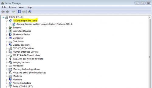
- Plug in the Mini USB cable from a USB port on your PC, to the J1 of the EVAL-SDP-CB1Z.

- Make sure that the computer installs the device drivers, and that you can see the ADI Development Tools in your computer's device manager.
- Next take the EVAL-SDP-CB1Z board and connect CON A up to J4 of the SDP-PMD-IB1Z interposer board. Ensure that you remove the shunt which is located at JP1 of the SDP-PMD-IB1Z

- Connect the EVAL-CFTL-6V-PWRZ to J1 barrel jack of the SDP-PMD-IB1Z, and WAIT 10 SECONDS before continuing

- Place the shunt across JP1 of the SDP-PMD-IB1Z, according to the silkscreen so that you will have 3.3V going to the PMOD connector.

- Take the PulSAR ADC PMOD board you are using and connect it to J3 of the SDP-PMD-IB1Z interposer board. This should finish the hardware setup.

- Check again in the device manager to make sure the ADI Development Tools are still displaying. If yes, than you'll be able to proceed onto the evaluation software section.


Labview Software Application (GUI interface explained)
The PulSAR ADC PMOD boards have a special version of software needed to run the evaluation, so please install this version of the software.
Once you download and install the software, you'll be able to launch the application and communicate with the hardware setup. When you open up the application the front screen will look like the following:

The following is the description of the user panel:
- File menu with choice of
- Load Data: load previously captured data
- Save Data as .tsv: save captured data in tsv (tab separated values) format for future analysis
- Save Picture: use to save the current screen capture
- Print
- Exit
- Once hardware is connected to the USB port, and the software application is running select the ADC you are using from the pull down list.
- Sampling Frequency: The default sampling frequency will match the maximum sample rate of the ADC connected to the board. The user can adjust the sampling frequency; however, there are limitations around the sample frequency related to the SCLK frequency applied. The sample frequency must be an integer divider of the SCLK frequency. In addition, where unusable sample frequencies are input, the software automatically adjusts the sample frequency accordingly. Units can be entered, such as 10k for 10,000 Hz. Because the maximum sample frequency possible is device dependent, with some of the ADCs capable of operating up to 250 kSPS, while others can go to 1.3 MSPS, the software will match the particular ADC ability. If the user enters a value larger than the ability of the existing device, the software will indicate this and revert to the maximum sample frequency.
- SCLK Frequency: The default SCLK frequency is set to 60 MHz, which is the maximum allowable from the SDP. The SCLK is applied to the ADC SCK pin. The SDP board limits the SCLK frequency, nominal values for correct operation are 60 MHz, 30 MHz, and 20 MHz. Where the user adjusts the SCLK/sample rate to values that are not supported by the SDP clock or the ADC sample rate, the software overrides by adjusting values accordingly and identify this to the user. The SCLK frequency will be rounded down.
- External reference voltage. By default, this reference is 5V (ADR435 on board reference). The min/max voltage calculations are based on this reference voltage. If user changes the reference voltage, then they should change this input accordingly.
- “Read” : to perform a single capture
- “Start” : to perform a continuous capture from the ADC.
- “Stop”: to stop streaming data
- Select the number of samples to analyse, when running continuously, this number will be limited to 65536 samples.
- There are four tabs available displaying the data in different formats, this are listed here and described in more detail later.
- Waveform tab
- Histogram
- FFT
- Summary
Schematics, PCB Layout, Bill of Materials
- Schematics (PDF)
- Bill of materials (Excel)
- Layout (PDF)
- Assembly Drawing (PDF)
resources/eval/user-guides/circuits-from-the-lab/pulsar-adc-pmods.1461614292.txt.gz · Last modified: 25 Apr 2016 21:58 by Brandon Bushey