


This version is outdated by a newer approved version. This version (05 Jan 2022 05:45) is a draft.
Approvals: 0/1
This version (05 Jan 2022 05:45) is a draft.Approvals: 0/1
This is an old revision of the document!
Table of Contents
EVAL-ADPD410X-ARDZ User Guide
EVAL-ADPD4100-ARDZ and EVAL-ADPD4101-ARDZ are simple, Arduino form-factor breakout board for developing ADPD4100 and ADPD4101, respectively. The ADPD4101, interfaced through I2C, and the ADPD4100, interfaced through SPI, are highly versatile, multimodal sensor front ends, stimulating up to eight light emitting diodes (LEDs) and measuring the return signal on up to eight separate current inputs. There are a number of other evaluation platforms for these devices, including the EVAL-ADPD4100Z-PPG, optimized for photoplethysmograph applications, and the reference design CN0503, optimized for optical liquid analysis applications (colorimetry, turbidity, fluorescence). The EVAL-ADPD410X-ARDZ boards come in handy for adapting these evaluation boards to meet specific application requirements, as well as for “ground up” development of new applications.

Features
- 8 LED excitation channels with high-voltage extension circuitry
- 8 Photodiode inputs
Device Driver and Support
A no-OS device driver and example program is provided, targeting the EVAL-ADICUP3029 platform. The ADICUP3029 example application uses the ADPD410x no-OS driver, and emulates the Linux IIO framework through the tinyiiod daemon library. The application communicates with the host computer via the serial backend, over a USB-UART physical connection. This facilitates rapid application development on a host computer, independent from embedded code development. Similarly, utility software (iio_info, IIO Oscilloscope, PyADI-IIO, etc.) that are typically associated with Linux systems can be used with this no-OS implementation.
Materials Needed
- Micro USB to USB cable
- PC or laptop with a USB port
Driver / Firmware Setup
There are two basic ways to program the EVAL-ADICUP3029 with the software for both boards.
Dragging and Dropping the Hex File to the Daplink Drive
- Connect the EVAL-ADICUP3029 board to the PC or laptop using the Micro USB to USB cable.
- Drag and Drop the appropriate .hex file from the list below to the the Daplink Drive
- The drive will unmount once the .hex file is dropped and wait for it to reappear. Once it does, press the reset button of the EVAL-ADICUP3029 to ensure that the microcontroller is updated.

Confirm that these are the latest HEX files, and that they function with IIOscope and pyadi:
eval-adicup3029/releases/tag/Latest
Prerelease hex files can be found inside this zip archive: eval-adpd410x-ardz_hex_files.zip
- For EVAL-ADPD4100: ADuCM3029_demo_adpd4100_27_08_2021.hex
- For EVAL-ADPD4101: ADuCM3029_demo_adpd4101_27_08_2021.hex
Using CrossCore Embedded Studio
- You will have to acquire a copy of the project source files of the EVAL-ADPD410X-ARDZ. You can download the source files directly from the repository at EVAL-ADICUP3029/tree/dev/cn0567/projects/ADuCM3029_demo_cn0567 or you can clone the entire EVAL-ADICUP3029 repository and check the projects folder for ADuCM3029_demo_cn0567
- Open CrossCore Embedded Studio and import the project into your workspace as detailed in cces_user_guide. This allows you to edit the software to fit your requirements.
If this is your first time using CrossCore Embedded Studio, check the user guide to get you started
- Once ready, you can opt to generate your own .hex file and use the first method to program the EVAL-ADICUP3029 or you can use a debug session by following the quickstart guide.
Hardware Setup
Jumper Configurarion
There are two shunt-configurable jumpers and 3 types of solder jumpers on both EVAL-ADPD4100-ARDZ and EVAL-ADPD4101-ARDZ boards.
I/O Logic Voltage (IOSEL) Shunt Positions
| Correct Shunt Position | Layout Picture |
|---|---|
| Shorted Pin 1 and 2 |  |
Onboard LED and Photodiode (P10) Shunt Positions
| Correct Shunt Position | Layout Picture |
|---|---|
| Shorted Pin 1 and 2, Shorted Pin 3 and 4, Shorted Pin 5 and 6 |  |
LED Supply Voltage (JP1) Solder Positions
| Correct Shunt Position | Layout Picture |
|---|---|
| Shorted Pin 1 and 2 |  |
LED Driver Connection P9, P11, P13, P15, P17, P19, P22, P24
| Correct Shunt Position | Layout Picture |
|---|---|
| Shorted |  |
SPI or I2C Interface
| Board | Shorted Resistors | Layout Picture |
|---|---|---|
| EVAL-ADPD4100-ARDZ (SPI) | Shorted R8 and R9, Open R6 and R7 |  |
Below is a photo of the EVAL-ADPD4100-ARDZ (SPI) board with all the correct shunt and solder jumper connections.

| Board | Shorted Resistors | Layout Picture |
|---|---|---|
| EVAL-ADPD4101-ARDZ (I2C) | Shorted R6 and R7, Open R8 and R9 | 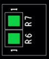 |
Below is a photo of the EVAL-ADPD4101-ARDZ (I2C) board with all the correct shunt and solder jumper connections.

Prototyping Connectors
The board has 2 parallel 18-pin 100-mil pitch male connectors which give access to the LED driver channels, the photodiode inputs, custom I/O pins from the AFE, and supply voltage for the LED. The user can use this along with the break-away protoboard to implement a custom circuit for test. The pin assignment and functions are shown below.

 Pins labeled XYC (where X refers to LED 1, 2, 3, or 4 and Y refers to channel A or B) pins denote connections to the LED cathode which are voltage protected via transistors to the ADPD4100/1 LED inputs (denoted by LXY). It is recommended to connect LED cathodes to this pins instead of connecting directly to LXY pins. PDXY (X refers to photodiode 1, 2, 3, or 4 and Y refers to channel A or B) pins denote photodiode signal inputs to the AFE. ACOM and BCOM pins refer to the common cathode bias output for photodiode sensors. These should be connected to the cathodes of photodiodes in the matching channel (i.e. photodiodes connected to PD1A, PD2A, PD3A, and PD4A should have their cathodes connected to ACOM).
A simple circuit for testing LED driver outputs and photodiode current sensing using the break-away prototype board can easily be set-up using optocouplers as shown below.

Software Setup
Installation
To communicate with the device from the PC or laptop using IIO commands, install the Libiio package by following the guide in the repository: libiio/releases. The method is different for Windows or Linux operating systems.
Connection
The device must be able to create a context. Context creation in the software depends on the backend used to connect the device. This guide will cover the device communication using a serial backend through a USB-UART connection. A simple way of checking, if the device is connected, is through the iio_info command. It reports all IIO attributes of a detected device and context. Simple enter the command shown below to a terminal / command line. iio_info -u serial:<serial port> Examples:
- In a Windows machine, you can check the port of your ADICUP3029 via Device Manager in the Ports (COM & LPT) section. If your device is in COM4, you have to use iio_info -u serial:COM4 as your URI.
- In a Unix-based machine, you will see it under the /dev/ directory in this format “ttyUSBn”, where n is a number depending on how many serial USB devices attached. If you see that your device is ttyUSB0, you have to use serial:/dev/ttyUSB0 as your URI.
IIO Oscilloscope
PyADI-IIO
Schematic, PCB Layout, Bill of Materials
EVAL-AD410X-ARDZ Design & Integration Files
- Schematics
- PCB Layout
- Bill of Materials
- Allegro Project
Additional Information and Useful Links
End of Document
resources/eval/user-guides/circuits-from-the-lab/eval-adpd410x.1641357955.txt.gz · Last modified: 05 Jan 2022 05:45 by Angelo Nikko Catapang