


This version (03 Mar 2023 00:54) was approved by Joyce Velasco.The Previously approved version (02 Mar 2023 01:28) is available.
Table of Contents
EVAL-AD5770R-PMDZ Hardware User Guide
The EVAL-AD5770R-PMDZ is a minimalist SPI Pmod board for the AD5770R. This module is designed as a low cost alternative to the fully featured AD5770R evaluation board and has no extra signal conditioning for the DAC.
About the AD5770R
The AD5770R is a 6-channel, 14-bit, multi-range, current output DAC designed for use in communications systems, instrumentation and industrial applications; specifically for photonics control and current mode biasing. It has 6 programmable output channels with 1 channel capable of sinking up to 60 mA of current.

Basic Hardware Setup
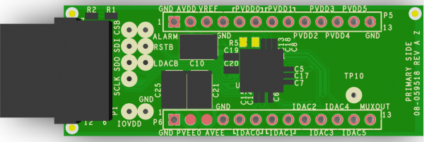
This section contains the configuration and descriptions for each of the EVAL-AD5770R-PMDZ connectors, as well as how to make the necessary connections for proper operation. Please note that connectors P5 and P6 are included with the board but left unsoldered. This gives the user the option of either using the provided connectors or directly soldering wires onto the board for their design.
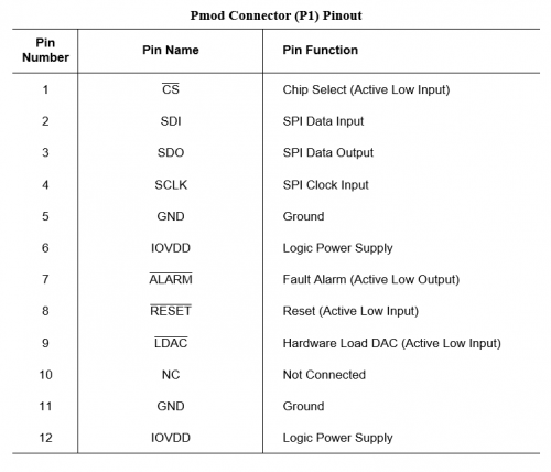
P1 connects the digital pins of the AD5770R to a system board, e.g. EVAL-ADICUP3029. Test vias are provided for each of these pins which could be used for debugging purposes. For a full description of each digital pin, refer to the AD5770R datasheet.

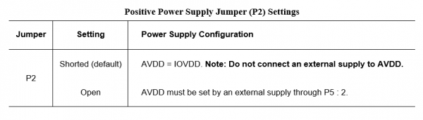
The pins of connector P5 are mapped to the supply pins of the AD5770R. By default, the EVAL-AD5770R-PMDZ uses the supply voltage from the controller board for AVDD/DVDD and IOVDD.


An external power supply can be used for AVDD/DVDD instead of the system power if jumper P2 is open.

Below are the voltage ranges for the positive supplies:
- AVDD : 2.9 V to 5.5 V
- PVDDx : 0.8 V to AVDD - 0.4 V
Unlike the AD5770R evaluation board, the EVAL-AD5770R-PMDZ has no onboard power solution for the PVDDx pins so these must be connected to external supply voltages. All PVDDx pins can be connected to the same supply; however, the supplied voltage should be enough so that the load voltages on each IDACx pin falls within the output compliance voltage of the corresponding channel (as specified on the AD5770R datasheet).
An example for single PVDDx supply:
If PVDD0 to PVDD5 are all connected to +2.000 V, the maximum load voltage for each channel would be:
- Channel 0 : +1.550 V
- Channel 1 : +1.725 V (140 mA; low headroom mode)
- Channel 1 : +1.550 V (250 mA, 140 mA; low noise mode)
- Channels 2 to 5 : +1.725 V
Pin 3 of connector P5 is mapped to the VREF pin of the AD5770R. Connect a reference voltage to this pin if the DAC is configured to use an external reference. Alternatively, the internal +1.25 V reference can be made available on this pin for use as a system reference.
Pins 5 to 6 of connector P6 are mapped to the current output pins of the AD5770R. The available output current ranges for each channel are as follows:
- IDAC0 : 0 to 300 mA, -60 to 0 mA, -60 to 300 mA
- IDAC1 : 0 to 140 mA, 0 to 250 mA
- IDAC2 : 0 to 55 mA, 0 to 150 mA
- IDAC3 to IDAC5 : 0 to 45 mA, 0 to 100 mA
Output Current Scaling:
To increase the output current range, tie multiple IDAC channels together to add their output currents. However, the load voltage must still fall within the output compliance range of both pins.
To decrease the output current range, use the OUTPUT_RANGE_CHx register as detailed in the AD5770R datasheet. The full scale current can only be scaled down to 50% of its nominal value.


If IDAC0 is configured to sink current, jumpers P3 and P4 should be open and external voltage supplies must be applied to the AVEE and PVEE pins on P6.


Below are the voltage ranges for the negative supplies:
- AVEE : -3.0 V to 0 V
- PVEE0 : AVEE to 0 V
The internal output monitor multiplexer of the AD5770R is available on pin 13 of P6. Depending on the values set programmed into the MONITOR_SETUP register of the AD5770R, this pin can be used to monitor either the output compliance voltage or the output current of a selected IDAC channel, or the internal die temperature of the device.
Refer to the AD5770R datasheet for how to translate the MUXOUT voltage into the aforementioned parameters.
Useful Links
AD5770R Pmod Software & Demo Application
The following link provides a simple demo application developed for the EVAL-AD5770R-PMDZ using the EVAL-ADICUP3029 development platform. The software provides the user with basic control over the onboard AD5770R through serial communication.
Schematic, PCB Layout, Bill of Materials
EVAL-AD5570R-PMDZ Design & Integration Files
- Schematic
- PCB Layout
- Bill of Materials
- Allegro Project
Registration
Receive software update notifications, documentation updates, view the latest videos, and more when you register your hardware. Register to receive all these great benefits and more!
End of Document
resources/eval/user-guides/circuits-from-the-lab/eval-ad5770r-pmdz.txt · Last modified: 03 Mar 2023 00:54 by Joyce Velasco