


This version (29 Sep 2023 08:18) was approved by Trisha Cabildo.The Previously approved version (27 Apr 2023 03:49) is available.
Table of Contents
EVAL-CN0566-RPIZ Hardware User Guide
CN0566 is a phased-array beamforming antenna demonstration platform that allows the user to experience the principles and applications of phased array antennas.
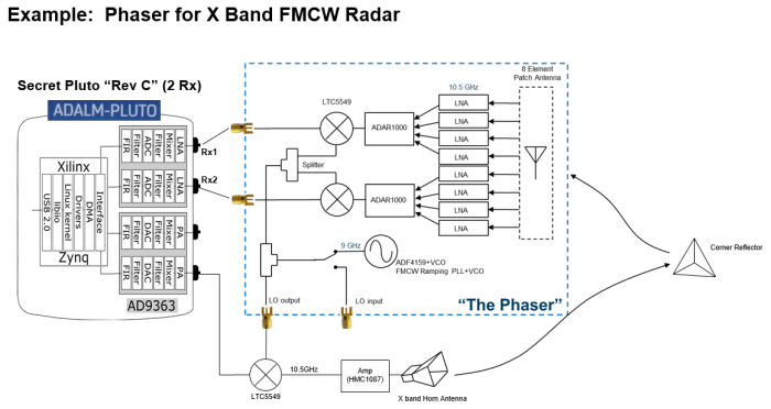
The RF input signal is received from an onboard 8-element patch antenna that operates from 10 to 10.5 GHz. Each antenna element is input to an ADL8107, a low noise amplifier (LNA) that operates from 6-18GHz with 1.3dB NF and 24 dB gain. The output of these amplifiers is fed into the main core of this circuitry, two of the ADAR1000. The ADAR1000 is an 8 GHz to 16 GHz, 4-Channel, beamformer that allows per-channel, 360° phase adjustment with 2.8° resolution, and 31dB gain adjustment with 0.5dB resolution. The ADAR1000s are capable of bidirectional, half-duplex operation. However, CN0566 only connects the ADAR1000 receive paths. The outputs of four LNAs get phase and amplitude shifted by an ADAR1000, then summed together at its RFIO output.
The ADAR1000's RFIO output passes through a low pass filter before entering the LTC5548 mixer. The low pass filter removes the high side image of the mixer as well as any re-radiation of the high side LO. LTC5548 outputs an IF of approximately 2.2 GHz which passes through a low pass filter (LPF) to remove mixer spurs and attenuate any RF or LO leakage. The LPF's output, at Rx1 and Rx2, can then be mixed down and sampled by an external 2-channel SDR receiver, such as the ADALM-Pluto.
The system consists of the EVAL-CN0566-RPIZ, Raspberry Pi 3 or 4 running ADI Kuiper Linux, an ADALM-Pluto Rev. C, 5V power source, and either keyboard/mouse/monitor OR separate host connected via VNC. The Raspberry Pi 4 provides all SPI, I2C, and discrete digital I/O control signals.

Figure 1. EVAL-CN0566-RPIZ Hardware
Features
- Provides CN0566 software control via Raspberry Pi w/ Kuiper Linux
- Includes a 10-10.5 GHz onboard antenna array design but with the option to connect your own antenna
- Supports applications running GNURadio, Python, or MATLAB
Videos
Documents Needed
- CN0566 Circuit Note
Equipment Required
- Hardware
- EVAL-CN0566-RPIZ Board
- Raspberry Pi 4
- ADALM-Pluto
- 5 V, 3 A, USB-C wall adapter
- HB100 microwave source
- Micro HDMI to HDMI adaptor
- HDMI to HDMI cable
- 16GB or larger SD card
- USB keyboard and mouse
- Monitor with HDMI display
- Tripod
- Software
- ADI Kuiper Linux image
Block Assignments
 Figure 2. EVAL-CN0566-RPIZ Circuit Evaluation Block assignment
- Connector P1 is the 14-pin header for connection to ADALM-Pluto
- Connector P16 is the type C port for the supply
- Connector RX1 is the SMA connector for RX1 output
- Connector RX2 is the SMA connector for RX2 output
- Connector TX_IN is the SMA connector for TX input
- Connector TX_OUT_1 is the SMA connector for the first TX output
- Connector TX_OUT_2 is the SMA connector for the second TX output
- Connector LO_OUT is the SMA connector for the LO output
- Connector EXT_LO is the SMA connector for external LO input
- Connector J3 to J10 are the footprints for SMP connectors in case an external antenna is to be used
Running the System
 Figure 3. Test Setup Functional Block Diagram
- Connect ADALM-Pluto to Raspberry Pi via micro-USB to USB cable.
- Connect the Raspberry Pi to the monitor via the HDMI cable.
- Connect the keyboard and mouse to the USB port of Raspberry Pi.
- Burn the SD card with the latest ADI Kuiper Linux image. Insert the flashed SD card into the designated slot on the Raspberry Pi.
- Setup the ADALM-Pluto. See Pluto setup section for detailed instructions.
- Power up the setup through the type-C port of the CN0566. No need to connect a supply to Raspberry Pi.
- Wait for Raspberry Pi to boot. Upon booting, open a terminal as seen on the taskbar.
- Configure the device tree overlay file. See software section for detailed instructions.
- Make sure to reboot the Raspberry Pi after saving the config.txt file.
- Wait for the Raspberry Pi to boot up again.
Pluto Setup
A Pluto Rev C or higher is required. For the CN0566, a custom firmware image is used that incorporates a TDD engine and additional control signals.
REMOVE this when it's got a proper home on Github releases
The first step is to update the firmware to the latest release, following the procedure at:\
Pluto/M2k Firmware Updates. Make sure to upload the entire zip file, not the pluto.frm contained within.
Next, download and unzip the updated firmware image, located here:
pluto_dw_march_16_2022.zip
(Yes, unzip, UNlike upgrading to the latest release.)
Drag and drop the pluto_DW_feb_7_2022.frm to the Pluto mass storage device, then eject.
For Reference - OLD version (do NOT use):
pluto_dw_march_9_2022.zip
pluto_dw_feb_7_2022.zip
The next step is to update the Pluto configuration to enable the AD9361's second channel. Follow the directions at:
Updating to the AD9364,
For setting the mode of a Rev. C PlutoSDR to 2r2t, the following would be sequence of commands:
Verify that the configuration was programmed properly by entering the following commands:
fw_printenv attr_name
fw_printenv attr_val
fw_printenv compatible
fw_printenv mode
Wihich should return:
# fw_printenv attr_name
attr_name=compatible
# fw_printenv attr_val
attr_val=ad9361
# fw_printenv compatible
compatible=ad9361
# fw_printenv mode
mode=2r2t
#
SD card / Software Setup
Loading CN0566 Image on SD Card
In order to control the CN0566 from the Raspberry Pi, you will need to install ADI Kuiper Linux on an SD card. Complete instructions, including where to download the SD card image, how to write it to the SD card, and how to configure the system are provided at Analog Devices Kuiper Linux. Pay particular attention to the localization settings, keyboard settings, etc. if you will be running examples on the Raspberry Pi itself (versus remotely.)
Write the image and follow the system configuration procedure.
Configuring the SD Card
After burning the image above, log into the Raspberry Pi and open the Raspberry Pi configuration utility.
Set the hostname to “phaser”, set the locale, keyboard, and wifi country (if you'll be connecting to your network by wifi.)
Next, run the following commands (and take a look at the setup script if you're suspicious, and note that there may be some updates as newer versions of Kuiper Linux are released.)
wget https://github.com/mthoren-adi/rpi_setup_stuff/raw/main/phaser/phaser_sdcard_setup.sh
sudo chmod +x phaser_sdcard_setup.sh
./phaser_sdcard_setup.sh
SKIP AHEAD to running the example, or see below for details of what just happened.
A complete config.txt file is posted for convenience. Enter the following commands from a terminal to download and apply a complete config.txt file with all edits above included:
wget https://github.com/mthoren-adi/rpi_setup_stuff/raw/main/phaser/config_phaser.txt
rename config_phaser.txt config.txt
sudo mv /boot/config.txt /boot/config_original.txt
sudo cp config.txt /boot/
Or alternatively, follow the Hardware Configuration procedure under Preparing the Image: Raspberry Pi in the Analog Devices Kuiper Linux page, adding the following lines to the very end of /boot/config.txt:
# Phaser board overlay:
dtoverlay=rpi-cn0566

# Heartbeat blinky:
dtparam=act_led_gpio=26
dtparam=act_led_trigger=heartbeat

# Short GPIO121 (pin 40) to ground for shutdown:
dtoverlay=gpio-shutdown,gpio_pin=21,active_low=1,gpiopull=up
If you will be logging in via VNC, comment out the following line, and set the HDMI group and mode accordingly:
# dtoverlay=vc4-kms-v3d

# uncomment to force a specific HDMI mode (this will force 1920x1080)
hdmi_group=2
hdmi_mode=82
PyADI-IIO
PyADI-IIO is a python abstraction module for ADI hardware with IIO drivers to make them easier to use. This module provides device-specific APIs built on top of the current libIIO python bindings. These interfaces try to match the driver naming as much as possible without the need to understand the complexities of libIIO and IIO.
Follow the step-by-step procedure on how to install, configure, and set up PYADI-IIO and install the necessary packages/modules needed by referring to this link.
Running the example
At this point, the GUI can be run from the command line. Run the following commands:
cd ~/pyadi-iio/examples/cn0566
python3 cn0566_gui.py
The GUI should load and begin displaying the beam pattern as shown below.
 Figure x. Phaser GUI
Initial Calibration
The phaser board is initially uncalibrated; each element will have a slightly different gain and slight phase error due to numerous factors. the cn0566_examples.py script provides a calibration utility that will generate calibration files. Make sure an antenna is attached to J1, and is facing straight at the antenna array from approximately 1.5m away. Then run:
python3 cn0566_examples.py cal
The script provides debug information and plots as it is running, you may have to close out of each plot for the script to proceed. After running this script, files gain_cal_val.pkl and phase_cal_val.pkl will be placed in the working directory. The GUI program will also load these files automatically.
Refer to CN0566 Calibration for additional details
Make sure to have the latest version of IIO Oscilloscope. Complete instructions and update scripts are found at Analog Devices IIO Oscilloscope.
CN0566 Configuration/Setup Examples


More Information and Useful Links
Schematic, PCB Layout, Bill of Materials, Casing
EVAL-CN0566-RPIZ Design & Integration Files
- Schematics
- PCB Layout
- Bill of Materials
- Assembly Drawing
- Allegro Project
Additional Information
resources/eval/user-guides/circuits-from-the-lab/cn0566/overview_setup.txt · Last modified: 29 Sep 2023 08:18 by Trisha Cabildo