


This version (29 Jul 2021 07:43) was approved by Zuedmar Arceo.The Previously approved version (19 Apr 2021 11:54) is available.
Table of Contents
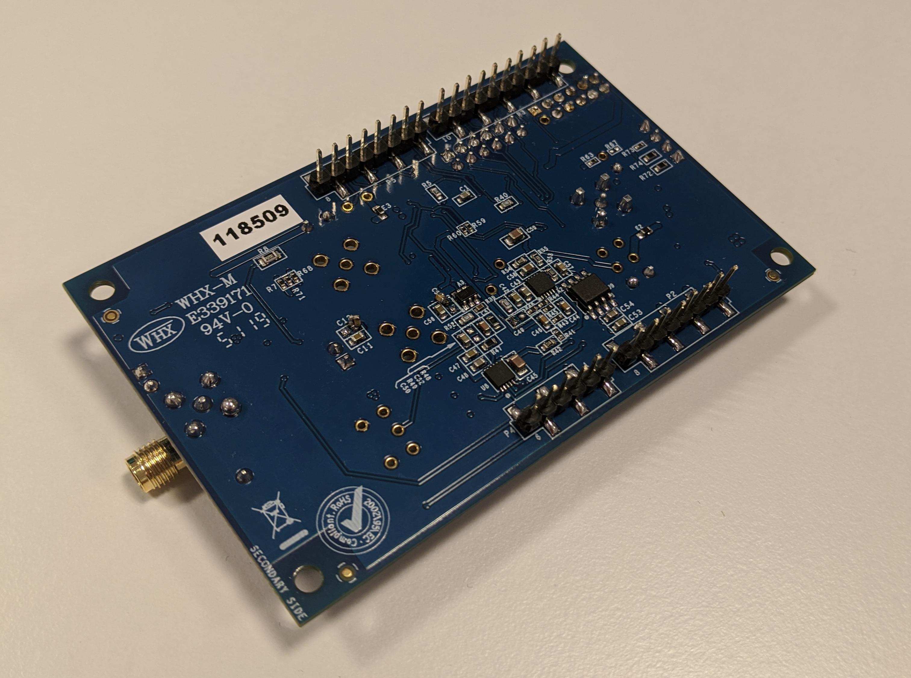
EVAL-CN0540-ARDZ Shield Overview
Monitoring the health of machinery can help predict changes in a machine’s condition. There are many methods of tracking a machine’s condition, but vibration analysis is the most commonly used one. By tracking the vibration analysis data over time, one can determine when a fault or failure is going to occur, along with the source of the fault. Knowing the condition of a certain machine will help not only increase efficiency and productivity, but create a safer working environment.
The reference design shown below, shows a high resolution, wide-bandwidth, high dynamic range, Integrated Electronics Piezoelectric (IEPE) compatible interface data acquisition system (DAQ) for interfacing with Integrated Circuit Piezo (ICP)/IEPE piezo vibration sensors. Most solutions which interface with piezo sensors in the market are AC coupled, lacking DC and sub-hertz measurement capability. This reference design is a DC coupled solution in which DC and sub-hertz precision are achieved.
By looking at the complete data set from the vibration sensor in the frequency domain (DC – 50 kHz), the type and source of a machine fault can be better predicted using the; position, amplitude and number of harmonics found in the FFT spectrum.
The data acquisition board incorporates a precision 24-bit, 1024kSPS Sigma-delta ADC AD7768-1 and a 16-bit voltage output DAC LTC2606. Used as the ADC driver is a high linearity FDA ADA4945-1 and a 200mA programmable 2-terminal current source LT3092. Analog input protection is provided by the switch ADG5421F. The data acquisition board is an Arduino compatible form factor, and can be interfaced and powered directly from most Arduino compatible development boards.
This user guide will discuss how to use an Arduino compatible micro-controller board and evaluation software to configure and collect vibration data from the EVAL-CN0540-ARDZ Shield (CN0540 Board).

Simplified functional block diagram

Features
- Data acquisition solution fully characterized over -25°C to 85°C.
- Throughput of 1024kSPS.
- DC coupled for greater precision.
- Powered and interfaced directly through an Arduino compatible development board.
Documents Needed
- Data Sheet
- CN0540 Circuit Note
General Setup
Jumper Placement
The EVAL-CN0540-ARDZ Shield (CN0540 Board) includes a jumper that should the user should be sure is placed in the correct position on P10. This jumper connects the current source to the circuit and may be removed for testing without a current source. (Placeholder for picture)
Sensor Input
The main input on the CN0540 is a right-angle SMA connector on the front of the board, as such it is highly recommended to connect the sensor using an SMA cable. If this is not possible, due to the type of sensor or otherwise, there is also the header P1 which can be connected to with standard wires. The software detailed below has an option to compensate for the voltage offset caused by a connected sensor which should always be run after connecting a new sensor.
LED Indicators
On the CN0540 board there are four LED lights. The PWR LED in the bottom-left corner indicates if the board is currently powered. LED1 and the CC LED, located in the top-right corner, indicate that the board is connected through the Arduino connectors. The FAULT LED is located just below them and indicates whether or not the switch's fault flag is raised.
Arduino Interface
All connector pinouts for the EVAL-CN0540-ARDZ are described in the table below.
| Connector | Pin No. | Pin Name | CN0540 Pin Function |
|---|---|---|---|
| Arduino DIO High | 1 | SCL | SCL |
| 2 | SDA | SDA | |
| 3 | AREF | NC (Not connected) | |
| 4 | AGND | DGND | |
| 5 | SCLK | SCLK | |
| 6 | MISO | DOUT_RDYB | |
| 7 | MOSI | SDI | |
| 8 | CS | CS_ADC | |
| 9 | RDY | SHUTDOWN | |
| 10 | IO28 | NC | |
| Arduino DIO Low | 1 | IO08 | RESET_ADC |
| 2 | IO27 | SYNC_IN | |
| 3 | IO33 | CSB_AUX | |
| 4 | IO09 | SW_FF | |
| 5 | IO13 | DRDY_AUX | |
| 6 | IO15 | DRDY | |
| 7 | TX | LED1 | |
| 8 | RX | LED2 | |
| Arduino Analog | 1 | AIN0 | IO5 |
| 2 | AIN1 | IO4 | |
| 3 | AIN2 | IO3 | |
| 4 | AIN3 | NC | |
| 5 | AIN4 | NC | |
| 6 | AIN5 | IO0 | |
| Arduino Power | 1 | NC | NC |
| 2 | IOREF | IOREF | |
| 3 | RESET | NC | |
| 4 | 3.3V | 3V3 | |
| 5 | 5V | NC | |
| 6 | GND | GND | |
| 7 | GND | GND | |
| 8 | Vin | NC |
Piezo Accelerometer Sensor Results
To achieve reasonable noise measurements, the piezo accelerometer must be either stabilized using an active shaker table which cancels environmental vibrations or anchored to a massive object which makes sensor still. Anchoring to a massive object was used for a following measurements, where the piezo accelerometer was connected directly to the input of the signal chain.
The following figures show DC and AC coupled solution comparison, where the DC coupled version is producing more noise, but it is more linear. Whereas the AC coupled is nonlinear at very low frequencies (a spike near DC frequency bin), caused by a coupling capacitor.

FFT for the DC coupled solution with passively stabilized piezo sensor connected.

FFT for the AC coupled solution with passively stabilized piezo sensor connected.
(Optional) Hardware Interface
The board includes many ways in its hardware to interface with the components. These are optional interfaces that can be used to externally control aspects of the components.
| Connector | Description |
|---|---|
| P7 | Externally control the shift voltage, used in the piezo sensor bias voltage correction. |
| J2 & J3 | Allows the user to input voltage while bypassing the front-end, directly into the ADC driver. |
| J4 | Externally provide the MCLK. |
| P6 | Allows the user to use I2C protocol to provide the voltage supply, the SCL and SDA. |
| P8 | PMOD connector allows the user to interface with the board without Arduino. |
| P9 | Allows the user to connect a digital MEMS microphone and interact with it using the Arduino connectors. |
Test Points
The board also has many test points, most of which are labelled and are fairly self-explanatory. The table below describes some of the most significant test points and their connections.
| Test Point | Description |
|---|---|
| TP5 | Connects to the 28V rail before it's reduced to 26V. |
| TP6 | Connects to the 7V rail before it's reduced to 5V. |
| TP7 | Connects to the +VS supply of the reference buffer. |
| TP8 | Connects to pin 10 on the Arduino DIO high connector. |
| IO1 | Connects to pin 5 on the Arduino Analog connector. |
| IO2 | Connects to pin 4 on the Arduino Analog connector. |
| GPIO0 | Connects to GPIO0 of the ADC. |
| GPIO1 | Connects to GPIO1 of the ADC. |
More Information and Useful Links
Schematic, PCB Layout, Bill of Materials
EVAL-CN0540-ARDZ Design & Integration Files
- Schematics
- PCB Layout
- Bill of Materials
- Allegro Project
Software Projects and Platforms
Registration
Receive software update notifications, documentation updates, view the latest videos, and more when you register your hardware. Register to receive all these great benefits and more!
End of Document
resources/eval/user-guides/circuits-from-the-lab/cn0540.txt · Last modified: 29 Jul 2021 07:43 by Zuedmar Arceo