 This version (09 Aug 2022 04:46) was approved by erbe reyta.The Previously approved version (09 Aug 2022 04:32) is available.
This is an old revision of the document!
Instruments that operate at RF range with features like low distortion, ultra low phase noise, and portable signal generator are difficult to provide at reasonable cost.
The system shown below in Figure 1 is an entirely self-contained DC to 6 GHz signal generator. It only requires the Raspberry Pi (RPi) to operate. The RF digital-to-analog converter (DAC), controlled using a 100 MHz Serial Peripheral Interface (SPI) from the RPi, allows for single tone, phase coherent, and fast frequency hopping across the spectrum. All the clocking requirements are generated using an on-board crystal, so no external clock source is needed. All the necessary power rails are also converted from the RPi into various supply voltage requirements of the RF signal generator.
The system is designed to simplify the input requirements, optimize signal paths, and reduce external cables and components. This circuit can act as a standalone laboratory equipment or can be incorporated as a module into automatic test equipment. Its small size makes it particularly attractive when multiple channels are required. This RPi-compatible solution makes high speed signal generation more accessible and economical.
Figure 1. EVAL-CN0511-RPIZ Evaluation Board
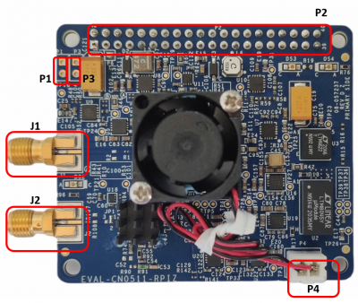 Figure 2. EVAL-CN0511-RPIZ Block Terminal Assignments
 Figure 3. Test Setup Functional Block Diagram
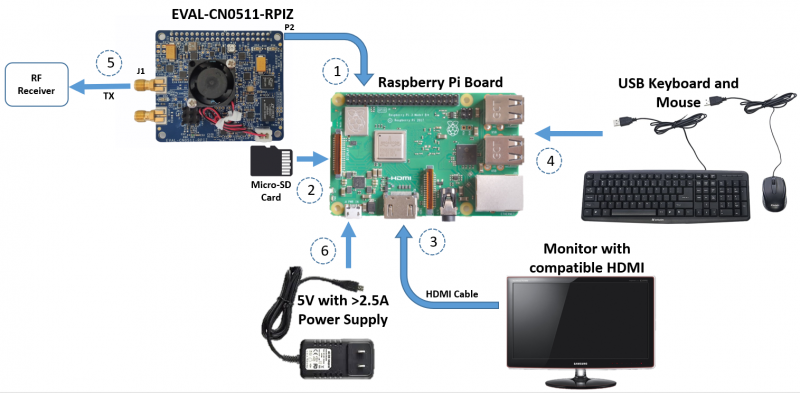
Figure 4. Hardware Connections of CN0511
To set up the circuit for evaluation, follow these steps:
The CN0511 reference design board is supplied with an ultra low phase noise CMOS, voltage-controlled crystal clock oscillator. If the performance requirements cannot be met, an external option is available, which is limited of up to 500 MHz clock source input. This external clock source can be connected through the on-board SMA port.
The CN0511 has a solder jumper (JP1) which configures different settings for the clock source, as shown below. The default position of JP1 is set at A-COM.
 Figure 5. EVAL-CN0511-RPIZ Clock Source Schematic Diagram
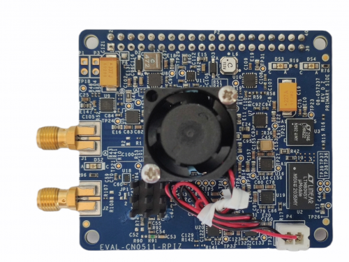
Figure 6. EVAL-CN0511-RPIZ Clock Source Assignment
RPi connects to the EVAL-CN0511-RPIZ through 40-pin connector P2.
 Figure 7. Input Power Supply Connection Options of CN0511
Figure 8. Input and Output Connection Guide of CN0511 Raspberry Pi with a Spectrum Analyzer and External Clock Source
The AD9166 is a high power device that can dissipate nearly 4 W depending on the user application and configuration. The EVAL-CN0511-RPIZ has a high cooling requirement; therefore, the fan should always be on to regulate the temperature below 60 degrees Celsius.
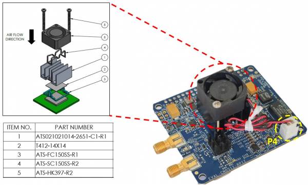 Figure 9. Cooling Management Guide of CN0511
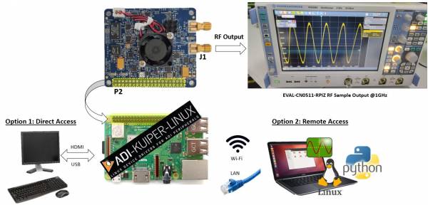 Figure 10. Overall System Setup Overview of CN0511
For the device to run, the SD card should have a preinstalled OS, which is the Analog Devices Kuiper Linux, a distribution based on Raspbian for the Raspberry Pi. It incorporates Linux device drivers for ADI products and is created with ease of use in mind. The reasoning behind creating this distribution is to minimize the barriers to integrating ADI hardware devices into a Linux-based system.
If a remote access in the device is required in an application, the CN0511 can be accessed through a remote PC connected either via LAN cable or Wi-Fi.
Once the device has been set up, the generated RFoutput from the CN0511 can be viewed at its output terminal.
In order to control the EVAL-CN0511-RPIZ from the Raspberry Pi, you will need to install ADI Kuiper Linux on an SD card. Complete instructions, including where to download the SD card image, how to write it to the SD card, and how to configure the system are provided at Kuiper Images. Write the image and follow the system configuration procedure.
For the Linux kernel to identify the device connected to the expansion header, update the device tree overlay. A Device Tree Overlay contains information about additional connected hardware, the EVAL-CN0511-RPIZ for this case. The overlay file is already included in the SD card and just needs to be matched to the EVAL-CN0511-RPIZ.
Follow the Hardware Configuration procedure under Preparing the Image: Raspberry Pi in the Kuiper Images page, substituting the following lines in config.txt:
This brings up the file in the terminal. Scroll down until the line that begins with “dtoverlay” is found; then, whatever it currently is, change it to:
dtoverlay=rpi-cn0511
Save the file by Ctrl + X command. Reboot the system by typing on the command prompt:
analog@analog:~$ sudo reboot
git clone https://github.com/analogdevicesinc/libad9166-iio
cd libad9166-iio
cmake ./CMakeLists.txt
make
sudo make install
cd bindings/python
sudo pip install -r requirements_dev.txt
cmake ./CMakeLists.txt
sudo make
sudo make install
Step 2: Clone the latest pyadi-iio from github
git clone https://github.com/analogdevicesinc/pyadi-iio
Step 3: Installation of libatlas-base-dev linux packages
sudo apt-get install libatlas-base-dev
Then choose 'Y' if were asked to continue.
After all these requirements has been loaded in the Raspberry Pi, example found in ~/home/analog/pyadi-iio/examples for CN0511 can now be run.
PyADI-IIO is a python abstraction module for ADI hardware with IIO drivers to make them easier to use. This module provides device-specific APIs built on top of the current libIIO python bindings. These interfaces try to match the driver naming as much as possible without the need to understand the complexities of libIIO and IIO.
This demo uses a PyADI-IIO example script. This scripts will show the single-tone frequency with calibrated output power in dBm.
.../pyadi-iio/examples $ python3 cn0511_example.py
Github link for the python sample script: CN0511 Python Example
The RPI_demo_cn0511 provides a solution for controlling RF output power and tuning from DC up to 6 GHz, using the EVAL-CN0511-RPIZ hat installed on an RPi base board. The user interface is implemented through wired and wireless connection.
The EVAL-CN0511-RPIZ can be evaluated with the IIO Oscilloscope. Customers can use the CN0511 plug-in tab, debug tab, and the DMM tab. Various controls and diagnostics are available in these plug-ins.
The CN0511 plug-in tab provides a simple user interface to control the EVAL-CN0511-RPIZ as a signal generator.

Figure 11. Graphical User Interface (GUI) window of ADI IIO Oscilloscope with CN0511 Plug-in
The debug tab provides direct access to IIO device and channel attributes, as well as the registers of the CN0511 components. The IIO attributes and registers can be read and written for advanced configuration and information.
The DMM tab provides temperature readings for ADF4372 and AD9166 using internal temperature sensors on both devices.
The DAC Data Manager set the DAC output scale for AD5693r that sets the bias on the on-board crystal oscillator.
EVAL-CN0511-RPIZ Design & Integration Files
Receive software update notifications, documentation updates, view the latest videos, and more when you register your hardware. Register to receive all these great benefits and more!
End of Document