


This version is outdated by a newer approved version. This version (01 Oct 2015 14:16) was approved by Ramon Glenn Amparo.
This version (01 Oct 2015 14:16) was approved by Ramon Glenn Amparo.This is an old revision of the document!
Table of Contents
CN0370 Evaluation Board and Software User Guide
Overview
CN0370 is a complete single-supply, low noise LED current source driver controlled by a 16-bit digital-to-analog converter (DAC). The system maintains ±1 LSB integral and differential nonlinearity and has a 0.1 Hz to 10 Hz noise of less than 45 nA p-p for a full-scale output current of 20 mA.
AD5542A is a single supply, 16-bit, serial input, voltage output DAC that is used to control the voltage to current conversion. ADA4500-2 is a single supply, dual low power amplifier with no zero-crossover distortion offering high linearity over the full, rail to rail common-mode input range. ADA4500-2 is used to buffer the reference voltage of the DAC and is also used in a buffer configuration to convert the voltage output of the DAC into current. ADR4525 is a high precision, low power, low noise voltage reference that is used to provide precise 2.5V reference voltage for the DAC.
This user guide will discuss how to use the EVAL-SDP-CB1Z, SDP-I-PMOD and the evaluation software to be able to write and collect data from EVAL-CN070-PMDZ. The evaluation board has provisions to read the output voltage of the DAC and an option to use an external supply voltage for the LED.
Required Equipment
- PC with a USB port and Windows XP or Windows Vista
- 32-b(it), or Windows 7 (32-bit)
- EVAL-SDP-CB1Z SDP evaluation board
- PMD-SDP-IB1Z interposer board
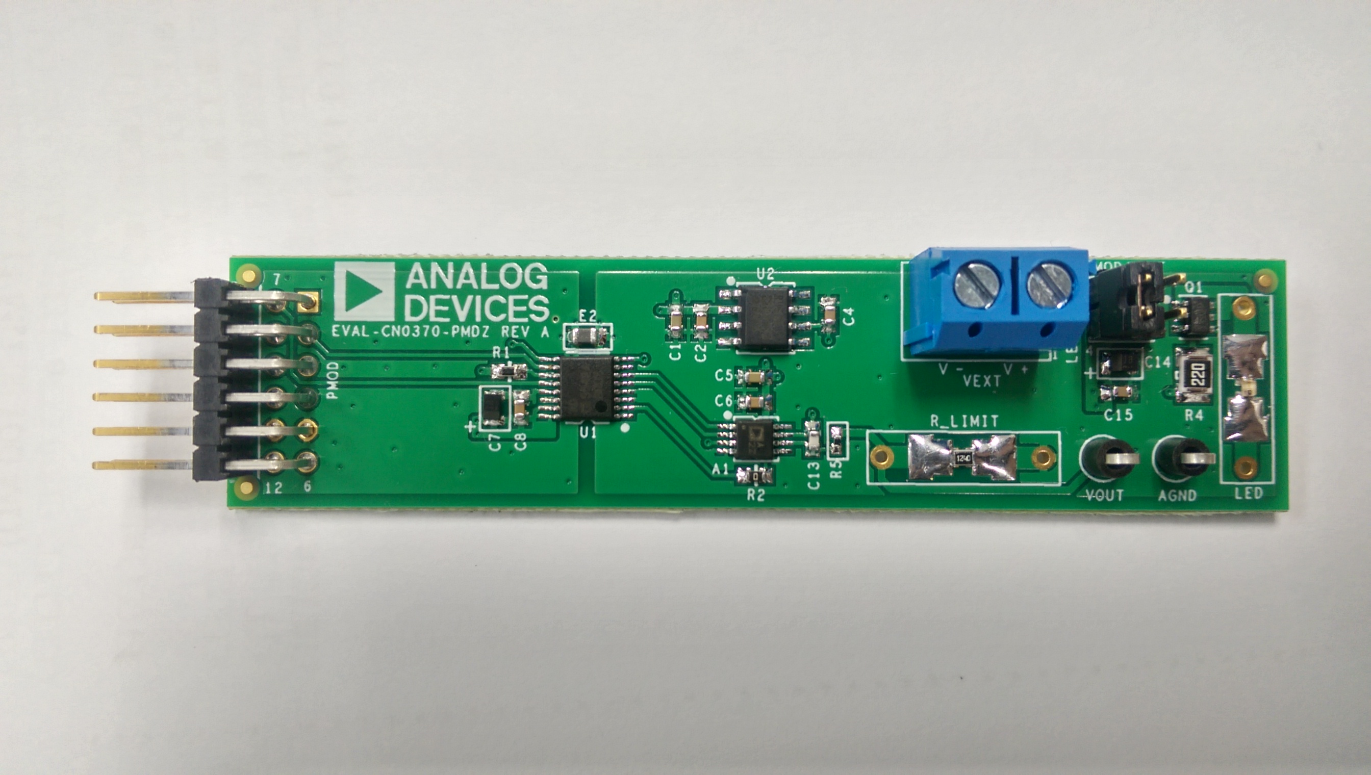
- EVAL-CN0370-PMDZ circuit evaluation board
- CN-0370 evaluation software:
- Power supply: 6 V wall wart.
- Agilent 34401A Multimeter or equivalent.
- A GPIB-to-USB cable (Required only when taking linearity tests for the circuit).
General Setup

- Connect the 120-pin connector J4 on the PMD-SDP-IB1Z interposer board to the connector marked CON A on the EVAL-SDP-CB1Z (SDP) evaluation board. Shunt on JP1 to be place on the +5.0V configuration.
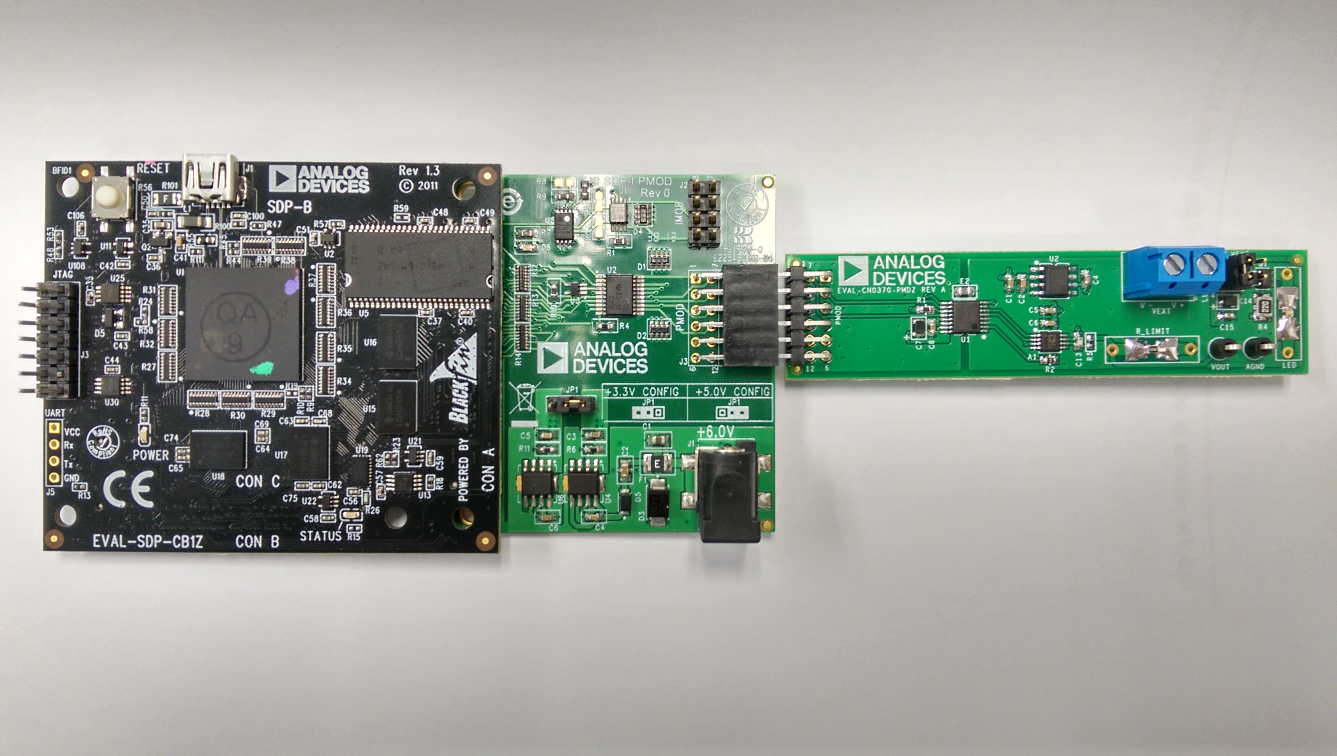
- Connect the EVAL-CN0370-PMDZ to the PMOD connector J3.
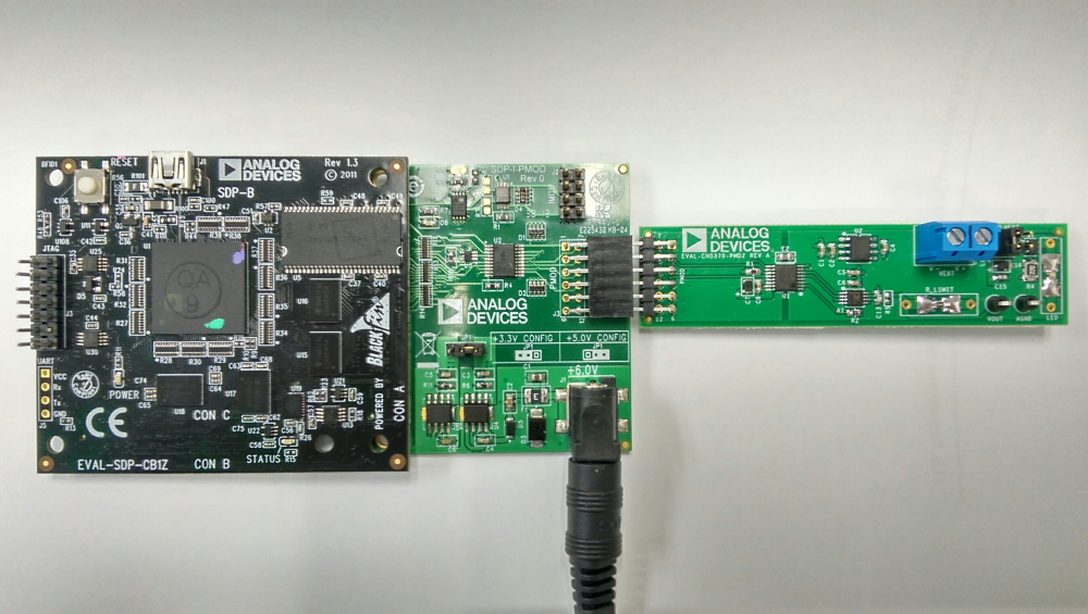
- Connect a +6V wall wart supply to the connector J1 of the interposer board.

- The USB cable is used to connect EVAL-SDP-CB1Z to the PC.

- LED_SUPPLY is the supply for the LED. It can be taken from the PMOD supply or an external voltage supply,VEXT. It is shorted by a shunt to PMOD by default.
- Test point VCC and AGDN are used to take voltage measurements.
- VEXT is used to supply an external voltage to the LED supply (Input range: +20max).
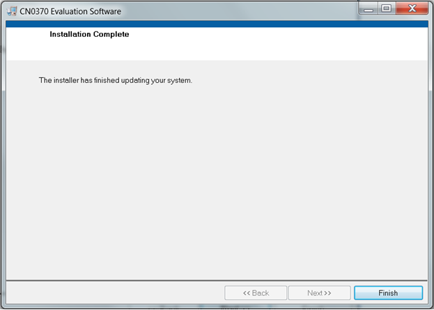
Installing the Software

- Extract the file CN0370_Evaluation_Software.zip and open the file setup.exe
- Click Next to view the installation review page

- Click Next to begin the installation
- Upon completion of the installation of the CN-0370 Evaluation Software, the installer for the ADI SDP Drivers will execute.

- Click Next to set the installation location for the SDP Drivers
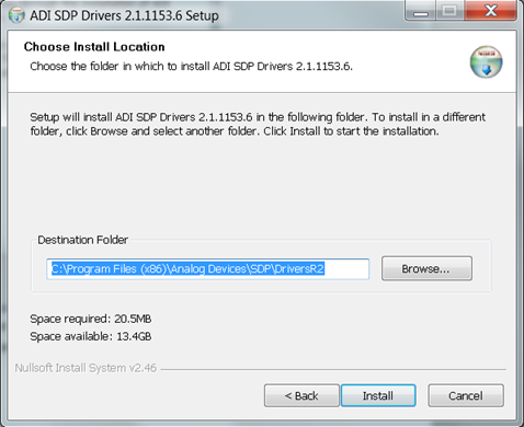
- Press Install to install the SDP Drivers and complete the installation of all software. Click Close when done.
Using the Evaluation Software
Main Tab

- Write data
- This button is used to write the data into the DAC
- Input Mode
- This is a selector where the user can choose the input mode of changing the amount of current or changing the actual DAC code being written
- Input Current Mode- the amount of current desired for the LED is adjusted and by pushing the Write Data button writes the data into the board.
- Input Code Mode- the exact code is written on the Code box, and the amount of current output is automatically adjusted by pushing the Write Data button.
- External Resistor
- Enable the external resistor if the resistor on R_LIMIT has been changed
- Iout
- This control will enable the user to change the amount of current flowing through the LED
- R_limit
- This is the value of the resistor that limits the amount of current through the LED, it is set to a default value of 124Ω
Writing data
Input Current Mode
- If the external resistor is replaced, enable the External Resistor button and write new value for the R_Limit.
- Select Input Current Mode.
- Adjust the amount of desired current by using the slider or the text box.
- Push the Write Data button to write the code to the board.
Input Data Mode
- If the external resistor is replaced, enable the External Resistor button and write new value for the R_Limit.
- Select the Input Code Mode.
- Write the exact code to be written in the Code text box.
- Push the Write Data button to write the code to the board.
resources/eval/user-guides/circuits-from-the-lab/cn0370.1442374317.txt.gz · Last modified: 16 Sep 2015 05:31 by Ramon Glenn Amparo