


This version is outdated by a newer approved version. This version (03 Jan 2021 22:00) was approved by Robin Getz.The Previously approved version (21 Jan 2015 08:10) is available.
This version (03 Jan 2021 22:00) was approved by Robin Getz.The Previously approved version (21 Jan 2015 08:10) is available.This is an old revision of the document!
Table of Contents
CN0364 Evaluation Board and Software User Guide
Overview
CN0364 is a complete, fully isolated,highly flexible, quad channel analog input system suitable for programmable logic controllers (PLCs) and distributed control system (DCS) applications that require multiple voltage inputs and HART-compatible, 4 mA to 20 mA current inputs.
The AD7173-8 24-bit Σ-Δ analog-to-digital converter (ADC) accepts the voltage and current input, and performs the data conversion. The AD5700-1 is the industry’s lowest power and smallest footprint HART-compliant modem and is used in conjunction with the current input channels to form a HART-compatible, 4 mA to 20 mA receiver solution. The ADG704 multiplexer provides HART connectivity to the multiple current input channels. The ADuM5211 and ADuM3151 provide digital line and power isolation. The ADP2441 36 V, step-down, dc-to-dc regulator accepts an industrial standard 24 V supply, with wide tolerance on the input voltage and steps it down to 5V to be used by the system.
This user guide will discuss how to use the EVAL-SDP-CB1Z and evaluation software to configure and collect data from the EVAL-CN0364-SDPZ Evaluation Board (CN-0364 Board). The evaluation board also has PMOD compatible headers for connection to other processors or microcontrollers.
A complete design support package for the EVAL-CN0364-SDPZ evaluation board containing schematics, layouts (native and Gerber), and bill-of-materials can be found at: CN0364-DesignSupport.

Required Equipment
- EVAL-SDP-CB1Z Controller Board (SDP-B Board)
- DC Power Supply (+12V to +24V)
- Precision voltage and current source (for input)
- PC with the following Minimum Requirements
- Windows Vista/7 (32-bit)
- USB type A Port
- Processor rated at 1GHz or faster
- 1GB RAM and 500 MB available hard disk space
- USB type A to USB type mini-B cable
General Setup

- The EVAL-CN0364-SDPZ (CN-0364 Board) connects to the EVAL-SDP-CB1Z (SDP-B Board) via the 120-Pin connector
- The EVAL-SDP-CB1Z (SDP-B Board) connects to the PC via the USB cable.
- Header P10 is a PMOD compatible SPI header - allows for communication to the ADC
- Header P11 is a PMOD compatible UART header - allows for communication to the HART modem
- Terminal block P9 is the power supply input (input range:+5.5V to +36V DC)
- Terminal blocks P1,P2,P3 and P4 provide the quad channel voltage input (-10V to +10V)
- Terminal blocks P5,P6,P7 and P8 provide the quad channel HART-compatible, 4 mA to 20 mA current inputs
See image for terminal block assignments:

Jumper Settings
- Jumper JP1
- INT - The evaluation is powered from header P9
- PMOD - The evaluation is powered from PMOD headers(P10 or P11)
- Jumper JP2
- VIO - digital logic level is set +3.3V coming from the SDP board
- VCC_PMOD - digital logic level is set by PMOD input (recommended is +3.3V or +5V)
Installing the Software
- Extract the file CN0364_Evaluation_Software.zip and open the file setup.exe.
NOTE: It is recommended that you install the CN-0364 Evaluation Software to the default directory path C:\Program Files\Analog Devices\CN0364\ and all National Instruments products to C:\Program Files\National Instruments\

- Click Next to view the installation review page

- Click Next to start the installation

- Upon completion of the installation of the CN-0364 Evaluation Software, the installer for the ADI SDP Drivers will execute.
NOTE: It is recommended that you close all other applications before clicking “Next”. This will make it possible to update relevant system files without having to reboot your computer.

- Press “Next” to set the installation location for the SDP Drivers.
It is recommended that you install the drivers to the default directory path
C:\Program Files\Analog Devices\SDP\Drivers

- Press “Next” to install the SDP Drivers and complete the installation of all software. Click “Finish” when done.

Using the Evaluation Software
Software Control and Indicator Descriptions
Main Tab

- Run/Stop
- Start/Stop data acquisition from the evaluation board
- Clear Data
- Clear the data on the chart and on voltage/current indicators
- Save Data
- Save the data collected to a tab delimited ASCII spreadsheet file
- Reset
- Reset the evaluation board and software to the defualt startup configuration
- Voltage/Current Numerical Display
- Displays the value of the voltage(V) and current(mA) per channel during data acquisition
- Chart
- Data plot for the data acquisition (may be displayed as voltage/current value or ADC code)
- Sampling Mode
- Real-Time - continuously capture a single sample per channel, and updates the display and chart
- Single Run - captures the specified number of samples and plots the data on the chart
- Display Units
- Voltage/Current - data on the chart is displayed as voltage/current values
- ADC Code - data on the chart is displayed as ADC codes
- Status Bar
- Displays a message to the user detailing the current state of the software There are three status LED colors:
 Inactive
 Busy
Busy
 Error
Error
Histogram Tab
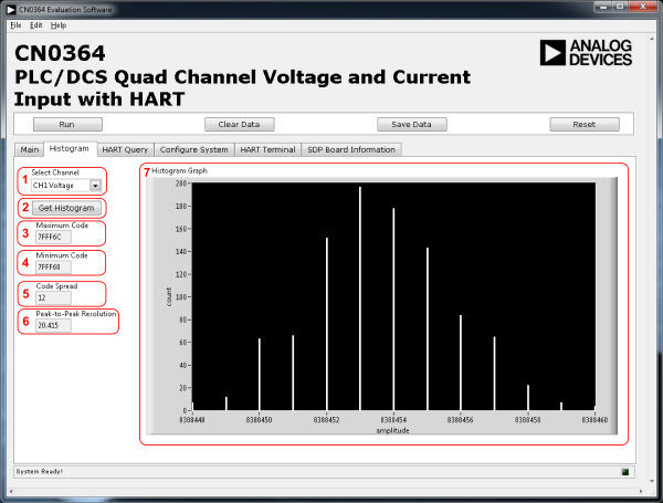
User needs to sample data first using Run to get histogram data on this page.
- Select Channel
- Channel selection for Histogram display
- Get Histogram
- Analyzes the data from the selected channel and displays the histogram data
- Maximum Code
- Display for the highest code from the sampled data of the selected channel
- Minimum Code
- Display for the lowest code from the sampled data of the selected channel
- Code Spread
- Display for the difference between the highest and lowest code from the sampled data of the selected channel
- Peak-to-Peak Resolution
- Display for computed Peak-to-Peak Resolution(bits) of the selected channel
- Histogram Graph
- Plot for the histogram data
HART Query Tab

- HART Channel
- Selection for the current input channel the HART enabled device is connected to
- Query Address CMD 0
- Queries the HART enabled devices address via a HART command 0
- Query Variables CMD 3
- Queries the HART enabled devices variables via a HART command 3
- Address Variable
- Display for the address variables received from the HART-enabled device via CMD 0
- Device Variables
- Display for the device variables received from the HART-enabled device via CMD 3
- Device Status
- Display for the reported status information from the HART enabled device
- Leave HART Transmit Switch Open
- By checking this both the Tx switch will not close between HART transmit messages. Due to the implementation of the HART output circuitry, this will not significantly affect the measurement accuracy as long at the loop bandwidth is <25Hz per the HART specification.
Configure System Tab

- Channel Control
- Control to enable/disable the input channels
- Current Input Control
- Control to select the filtering for the current input to the ADC
- Data Rate
- Control to set the output data rate of the ADC
- Digital Filter
- Control to set which digital filter is currently in use
- Sinc5 + Sinc1 Post Filter
- Control to select the data rate for the Sinc5 + Sinc1 post filter, Sinc5 + Sinc1 must be selected in the Digital Filter control for these settings to take effect
HART Terminal Tab

- HART Channel
- Selection for the current input channel the HART enabled device is connected to
- Command
- The full user specified command that should be transmitted including checksum as space delimitated text
- Write/Read and Write/Read continuously
- Sends the specified command and attempts to receive a response. The monitor window will show if a response was received.
- RX/TX Counters and Reset Counters Button
- Indicator for the number of RX/TX transactions
- Reset the send/receive counters to 0
- Monitor
- Display for the HART data that is sent and received
- Read and Read Continuously
- Queries if there a HART message in the receive buffer.
- Clear - Clears the monitor window
—-
Running the System
- Open the CN0364.exe application from the default installation location.
- The software will connect to the board automatically.
- Click the Run Button
- Click the Stop Button when acquisition is complete.
Saving Data to a Spreadsheet File
- Click the Save Data Button.
- Browse to the directory location where the spreadsheet file is to be saved.
- Name the file.
- Click the OK Button.
The software saves the spreadsheet file as ASCII text with columns separated by tabs
More Information and Useful Links
resources/eval/user-guides/circuits-from-the-lab/cn0364.1609707353.txt.gz · Last modified: 03 Jan 2021 21:55 by Robin Getz