


This version (15 Aug 2022 04:00) was approved by Allan Uy.The Previously approved version (29 Jul 2021 07:48) is available.
Table of Contents
CN0357 Software User Guide
Overview
CN-0357 is a single-supply, low noise, portable gas detector, using an electrochemical sensor. The Alphasense CO-AX Carbon Monoxide sensor is used in this example. Electrochemical sensors offer several advantages for instruments that detect or measure the concentration of many toxic gases. Most sensors are gas specific and have usable resolutions under one part per million (ppm) of gas concentration.
The circuit shown in below uses the ADA4528-2, dual auto zero amplifier, which has a maximum offset voltage of 2.5 µV at room temperature and an industry leading 5.6 µV/√Hz of voltage noise density. In addition, the AD5270-20 programmable rheostat is used rather than a fixed transimpedance resistor, allowing for rapid prototyping of different gas sensor systems, without changing the bill of materials. The ADR3412 precision, low noise, micropower reference establishes the 1.2 V common-mode, pseudo ground reference voltage with 0.1% accuracy and 8 ppm/°C drift. For applications where measuring fractions of ppm gas concentration is important, using the ADA4528-2 and the ADR3412 makes the circuit performance suitable for interfacing with a 16-bit ADC, such as the AD7790.
This user guide will discuss how to use the evaluation software to collect data from the EVAL-CN0357-PMDZ Evaluation Board (CN-0357 Board)

Required Equipment
- EVAL-SDP-CB1Z Controller Board (SDP-B Board)
- EVAL-CN0357-PMDZ Evaluation Board (CN-0357 Board)
- SDP-PMD-IB1Z Interposer Board (SDP to Pmod Interposer Board)
- EVAL-CFTL-6V-PWRZ (+6V Power Supply) or equivalent
- PC with the following Minimum Requirements
- Windows XP Service Pack 2 (32-bit)
- USB type A Port
- Processor rated at 1GHz or faster
- 512 MB RAM and 500 MB available hard disk space
- USB type A to USB type mini-B cable
General Setup
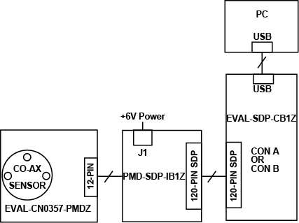
- The EVAL-CN0357-PMDZ (CN-0357 Board) connects to the SDP-PMD-IB1Z (SDP to Pmod Interposer Board) via the 12-Pin connector
- The SDP-PMD-IB1Z (SDP to Pmod Interposer Board) connects to the EVAL-SDP-CB1Z (SDP-B Board) via the 120-Pin connector
- The EVAL-CFTL-6V-PWRZ (+6V DC Power Supply) powers the SDP-PMD-IB1Z (SDP to Pmod Interposer Board) via the DC barrel jack
- The EVAL-SDP-CB1Z (SDP-B Board) connects to the PC via the USB cable.
Installing the Software
- Extract the file CN0357_Evaluation_Software.zip and open the file setup.exe.
NOTE: It is recommended that you install the CN0357 Evaluation Software to the default directory path C:\Program Files\Analog Devices\CN0357\ and all National Instruments products to C:\Program Files\National Instruments\

- Click Next to view the installation review page
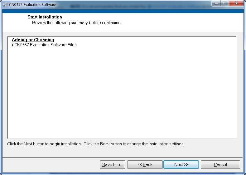
- Click Next to start the installation

- Upon completion of the installation of the CN-0357 Evaluation Software, the installer for the ADI SDP Drivers will execute.
NOTE: It is recommended that you close all other applications before clicking “Next”. This will make it possible to update relevant system files without having to reboot your computer.

- Press “Next” to set the installation location for the SDP Drivers.
It is recommended that you install the drivers to the default directory path
C:\Program Files\Analog Devices\SDP\Drivers

- Press “Next” to install the SDP Drivers and complete the installation of all software. Click “Finish” when done.

Connecting the Hardware
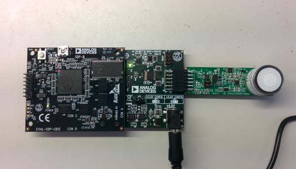
- Connect the EVAL-CN0357-PMDZ (CN0357 Board) to the SDP-PMD-IB1Z (SDP to Pmod Interposer Board) and the EVAL-SDP-CB1Z (SDP-B Board) to the SDP-PMD-IB1Z (SDP to Pmod Interposer Board) as depicted below.

- Connect the EVAL-CFTL-6V-PWRZ (+6V DC Power Supply) to the Barrel Jack at J1 on the SDP-PMD-IB1Z (SDP to Pmod Interposer Board)


Using the Evaluation Software
Software Control and Indicator Descriptions


- Run Button
- When this button is pressed, the SDP-B Board will collect concentration data and present the acquisitions in the chart.
- Stop Button
- When this button is pressed, the software stop collecting data from the CN0357 Board
- Save Data Button
- When this button is pressed, the software will save the data collected to a tab delimited ASCII spreadsheet file.
- Clear Data Button
- When this button is pressed, the software will clear all data collected from the chart history.
- Control Tabs
- Measure Concentration - Clicking this tab brings the data collection chart to the front.
- Configure System - Clicking this tab brings the system configuration settings to the front.
- SDP Board Information - Clicking this tab brings the SDP Board Information to the front.
- Concentration Numerical Indicator
- This indicator displays the current concentration measured by the system.
- Sensor Type Drop-down Menu
- Oxidation (sink) - Select this option if the sensor sinks current
- Reduction (source) - Select this option if the sensor sources current.
- Max Sensor Sensitivity Numerical Control
- The maximum amount of current in nanoamps (nA) the sensor will sink/source per part per million (ppm).
- This control influences the feedback resistance set by the Rheostat (AD5270).
- Typical Sensor Sensitivity Drop-down Menu
- The typical amount of current in nanoamps (nA) the sensor will sink/source per part per million (ppm).
- This control influences the size of the LSB in terms of ppm/mV and mV/ppm.
- Sensor Range Numerical Control
- The maximum concentration the sensor can measure in parts per million.
- Feedback Resistance Numerical Indicator
- ppm/mV Numerical Indicator
- Parts per million concentration per millavolt
- mV/ppm Numerical Indicator
- millavolts per parts per million concentration
- ADC Conversion Numerical Indicator
- The converted voltage seen by the ADC (AD7790).
- Chart Controls
- These controls allow the user to zoom-in, zoom-out, and pan through the data collected.
- System Status String Indicator
- This indicator displays a message to the user detailing the current state of the software.
- System Status LED Indicator
- This indicator displays the current state of the software in the form of an LED. There are three status LED colors.
 Inactive
 Busy
Busy
 Error
Error
- Buffer Mode Radio Buttons
- Buffered Mode - This allows the user to place source impedance on the front end without contributing to gain errors to the system.
- Unbuffered Mode - This disables the buffers, lowering the power consumption of the device.
Enabling the buffers also reduces the Analog Input Range of the ADC
- Mode Register Numerical Indicator
- This register is used to configure the ADC for range, enable or disable the buffer, or place the device into power-down mode.
- The Register Bit Designations can be found on Page 11 of the AD7790 Datasheet in Table 9.
- Filter Register Numerical Indicator
- This register is used to set the output word rate.
- Table 12 in the AD7790 Datasheet outlines the Register Bit Designations for the filter register.
The CN0357 Evaluation Software uses the Single Conversion Mode.
- Reset ADC Button
- The serial interface can be reset by writing a series of 1s on the DIN input.
- Reset returns the interface to the state in which it is expecting a write to the communications register.
- This operation resets the contents of all registers to their power-on values.
- Feedback Selector Radio Buttons
- Rheostat - Selecting this option uses the Rheostat for the feedback resistance of the transimpedance amplifier and disables the Fixed Resistor Numerical Control.
- Fixed Resistor - Selecting this option uses a fixed-resistor for the feedback resistance of the transimpedance amplifier and disables the RDAC Value Numerical Indicator, Rheostat Resistance Numerical Indicator and Program Rheostat Button.
- Fixed Resistor Numerical Control
- Input the value of the resistor populated at R7 if not using the Rheostat
- RDAC Value Numerical Indicator
- The value transmitted to the RDAC register of the Rheostat in hexadecimal format.
- Rheostat Resistance Numerical Indicator
- The equivalent resistance of the Rheostat.
- Program Rheostat Button
- Load the current RDAC value to the 50-TP Memory Block of the Digital Rheostat.
Programming the current RDAC value to 50-TP can only occur 50 times.
Running the System
- Open the CN0357.exe application from the default installation location.
- The software will connect to the board automatically.
- Click the Run Button
- Click the Stop Button when acquisition is complete.
Saving Data to a Spreadsheet File
- Click the Save Data Button.
- Browse to the directory location where the spreadsheet file is to be saved.
- Name the file.
- Click the OK Button.
The software saves the spreadsheet file as ASCII text with columns separated by tabs
Downloads
Registration
Receive software update notifications, documentation updates, view the latest videos, and more when you register your hardware. Register to receive all these great benefits and more!
resources/eval/user-guides/circuits-from-the-lab/cn0357.txt · Last modified: 15 Aug 2022 03:59 by Allan Uy