This is an old revision of the document!
CN0264 Evaluation Board Guide
Overview
CN0264, a circuit for transmitting composite video, is composed of digital-to-analog video converter paired with a low cost, low power, fully integrated reconstruction video filter with output short-to-battery (STB) protection, ideal for CVBS video transmission in harsh infotainment environments such as automotive applications.
ADV7391 is a high speed, digital-to-analog video encoder on single monolithic chip optimized for low power operation. It has an 8-bit video input port that supports SD video formats over a software defined radio (SDR) interface and HD video formats over a double data rate (DDR) interface. Three 2.7 V/3.3 V 10-bit video digital-to-analog converters (DACs) provide support for composite (CVBS), S-Video (Y-C), or component (YPrPb/RGB) analog outputs in either standard definition (SD) or high definition (HD) video formats.
ADA4432-1 and ADA4433-1 are fully integrated, single-ended and differential video reconstruction filters, respectively. They combine overvoltage protection (STB protection) up to 18 V on the outputs, with low power consumption and a wire diagnostic capability. Wire diagnostics are provided by way of a logic output that is activated when a fault condition is present. Both feature a high-order filter with a −3 dB cutoff frequency of 10 MHz and 45 dB of rejection at 27 MHz.
The ADV7391 and ADA4432-1 are fully automotive qualified, which makes both products ideal for infotainment and vision-based safety systems for automotive applications.
The EVAL-CN0264-EB1Z Board connects to mini-USB connector and is powered by a +7.5 V supply or +7.5 V “wall wart”.

Required Equipment
General Setup
Block assignments

-
Terminal block J1 is RCA jack for the video output
Terminal block
J2 is the +7.5
V barrel connector for wall wart supply input
Terminal block J3 is mini DIN connector for S-video input
Terminal block J4 RCA jack for the video input
Terminal block J5 is the jumper for power-down mode of ADV7180
Terminal block
J6 is mini AB
USB port connecting the board to PC
Terminal block J7 is the jumper for FIELD pin of ADV7180
Terminal block J8 is the Video Pixel Output Port of ADV7180. Has output configurations for 8-bit or 16-bit mode
Terminal block J9 is the RCA jack for CVBS input for ADA4830-2
Terminal block J10 is the jumper for logic high or low in the chip data address pin of serial EEPROM 24LC64
Terminal block J11 is the jumper for power-down/disable mode of ADA4417-3
Terminal block J12 is the jumper for output DC offset enable pin of ADA4417-3
Terminal block J13 is the RCA jack for CVBS input to ADA4433-1, a differential video filter
Terminal block J14 is the RCA jack for processed output CVBS signal in ADA4432-1
Terminal block J15 is the RCA jack for positive differential output of ADA4433-1, a differential video filter
Terminal block J16 is the RCA jack for negative differential output of ADA4433-1, a differential video filter
Terminal block J17 is mini DIN connector for S-video output of DAC1 from ADA4433-1
Terminal block J18 is the jumper for grounding second positive differential input of ADA4830-2
Terminal block J19 is the jumper for grounding second negative differential input of ADA4830-2
Jumper settings
See the table in the image below for the jumper settings. Values in red are the default settings for the EVAL-CN0264-SDPZ.

Jumper 8 is for the P7 to P0 Output/Input Pin Mapping of ADV7180. Table below summarizes the output/input mapping depending on chosen format and mode of operation.

Test setup

-
-
Connect the Universal Serial Bus (
USB) cable from your computer (the computer where ADV Register Control software is installed) to the mini
USB connector on the
EVAL-CN0264-SDPZ Evaluation Board. An LED near the
USB connector on the board should turn on.
Connect video input and output cables
Launch the evaluation software
Installing the Evaluation Software
Extract the file
CN0264_Evaluation_Software.zip and open the file
setup.bat.
NOTE: It is recommended that you install the software to the default directory path C:\Program Files (x86)\Analog Devices\ADV Register Control 7.0\ and all National Instruments products to C:\Program Files\National Instruments\

Click
Next to view the installation review page

Click
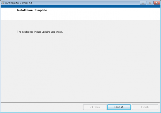
Next to start the installation

Using the Evaluation Software
Main Tab
Running the System
Open the ADV Register Control Software
When the ADV Register Control opens a window called ADV Register Program Configuration opens, make sure that the “USB Connected” indicator is green
If indicator doesn't light up, redo the power-up and connect to your computer sequence
Select the proper script according to the model type of your ADV7180. In the case of CN0264 board, ADV7180_ADV7180@_ADV7393-VER.1.0LQFP64.txt shall be selected.
To program the CN0264 evaluation board press Setting → Scripts
Select which script you want to run on the drop down menu. The desired script depends on the analog video inputted to the ADV7180, and the desired analog video output from the video encoder on the evaluation board
Schematic, PCB Layout, Bill of Materials
 This version (03 Jan 2021 22:05) was approved by Robin Getz.The Previously approved version (28 Dec 2017 07:59) is available.


