


This version is outdated by a newer approved version. This version (01 Apr 2013 23:39) was approved by James Fitzgerald.The Previously approved version (20 Mar 2013 21:06) is available.
This version (01 Apr 2013 23:39) was approved by James Fitzgerald.The Previously approved version (20 Mar 2013 21:06) is available.This is an old revision of the document!
Table of Contents
CN-0251 Software User Guide
Overview
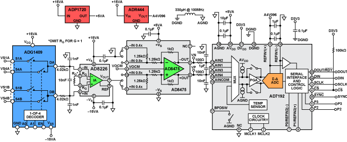
CN-0251 is a flexible signal conditioning circuit for processing signals of wide dynamic range, varying from several mV p-p to 20 V p-p. The circuit provides the necessary conditioning and level shifting and achieves the dynamic range using the internal programmable gain amplifier (PGA) of the high resolution analog-to-digital converter (ADC).
A ±10 V full-scale signal is very typical in process control and industrial automation applications; however, in some situations, the signal can be as small as several mV. Attenuation and level shifting is necessary to process a ±10 V signal with modern low voltage ADCs. However, amplification is needed for small signals to make use of the dynamic range of the ADC. Therefore, a circuit with a programmable gain function is desirable when the input signal varies over a wide range.
In addition, small signals may have large common-mode voltage swings; therefore, high common-mode rejection (CMR) is required. In some applications, where the source impedance is large, high impedance is also necessary for the analog front-end input circuit.
This user guide will discuss how to use the evaluation software to collect data from the EVAL-CN0251-SDPZ Evaluation Board (CN-0251 Board)
Required Equipment
- EVAL-SDP-CB1Z Controller Board (SDP-B Board)
- EVAL-CN0251-SDPZ Evaluation Board (CN-0251 Board)
- +6V Power Supply
- ±15V Dual Power Supply
-
- PC with the following Minimum Requirements
- Windows XP Service Pack 2 (32-bit)
- 2xUSB Type A Port
- Processor rated at 1GHz or faster
- 512 MB RAM and 500 MB available hard disk space
- USB Type A to USB Mini-B cable
- USB Type A to USB Micro-B cable
General Setup
- The EVAL-CN0251-SDPZ (CN-0251 Board) connects to the EVAL-SDP-CB1Z (SDP-B Board) via the 120-Pin connector at J5.
- The +6V Power Supply powers the EVAL-CN0251-SDPZ (CN-0251 Board) via the screw terminals at J3.
- The ±15V Dual Power supply powers the EVAL-CN0251-SDPZ (CN-0251 Board) via the screw terminals at J4.
- The EVAL-SDP-CB1Z (SDP-B Board) connects to the PC via the USB Type A to USB Mini-B cable.
- The Analog Discovery connects to the PC via the USB Type-A to USB Micro-B cable.
- The Analog Discovery connects to the EVAL-CN0251-SDPZ (CN-0251 Board) via the screw terminals at J1.
<html><br><br></html> <html><hr></html>
Connecting the Hardware
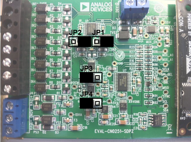
- Ensure the jumpers are populated on the EVAL-CN0251-SDPZ (CN-0251 Board) as depicted in the figure below.
- JP1 and JP2 configure the analog inputs for single-ended or differential inputs
- JP3 and JP4 configure the gain of the AD8475 to be 0.4x or 0.8x<html><br><br></html>
 <html><br><br></html>
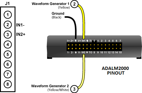
- Connect the Analog Discovery to the EVAL-CN0251-SDPZ (CN-0251 Board) as depicted in the figures below.
- The waveform outputs should be connected to J1:2 (IN1-) and J1:3 (IN2+) of the CN-0251 Board.<html><br><br></html>
- Connect the +6V Power Supply to the screw terminal at J3.
- Connect the ±15V Power Supply to the screw terminal at J4.
- Connect the SDP-B Board to the CN-0251 Board

Setting up Digilent WaveForms
- Install Digilent WaveForms Software
- Use the USB Type-A to USB Micro-B cable to connect the Analog Discovery to the PC
- Open the file named cn0251_demo.dwfawg<html><br><br></html>
 <html><br><br></html>
 - Click the Run All Button<html><br></html>


Using the Evaluation Software
Software Control and Indicator Descriptions

- <html><a id=“1”><b>Connect/Reconnect Button</b></a></html>
- When this button is pressed, the SDP-B Board makes a USB connection to the CN-0288 Board. A connection to the SDP-B Board must be made to use the software.
- <html><a id=“2”><b>Capture Data Button</b></a></html>
- When this button is pressed, the SDP-B Board will collect conversion data and present the acquisitions in the chart.
- <html><a id=“3”><b>Save Data Button</b></a></html>
- When this button is pressed, the software will save the data collected to a tab delimited ASCII spreadsheet file.
- <html><a id=“4”><b>Control Tabs</b></a></html>
- Data - Clicking this tab brings the data collection chart to the front.
- Analysis - Clicking this tab brings the data analysis histogram to the front.
- Configure System - Clicking this tab brings the system configuration control to the front.
- SDP Board Information - Clicking this tab brings the SDP Board Information indicators to the front.
- <html><a id=“5”><b>Input Channel Drop-Down Menu</b></a></html>
- Clicking this drop-down menu selects the channel to capture data from.
- <html><a id=“6”><b>Input Range Drop-Down Menu</b></a></html>
- Clicking this drop-down menu selects the analog input voltage range for the channel selected by the <html><a href=“#6”><b>Input Range Drop-Down Menu</b></a></html>.
- <html><a id=“7”><b>AD7192 Gain Indicator</b></a></html>
- This indicator displays the gain currently programmed into the AD7192.
- <html><a id=“8”><b>AD8475 Gain Indicator</b></a></html>
- This indicator displays the gain setting required from the AD8475.<html><br><br></html>
Jumpers JP3 and JP4 on the EVAL-CN0251-SDPZ (CN-0251 Board) must be populated to reflect the value displayed by this indicator
- <html><a id=“9”><b>Samples to Capture Control</b></a></html>
- This numerical control sets the number of samples to capture once the <html><a href=“#2”><b>Capture Data Button</b></a></html> is pressed.
- <html><a id=“10”><b>Display Unit Drop-Down Menu</b></a></html>
- Clicking this drop-down menu allows you to select chart y-axis units to display.
- <html><a id=“11”><b>Chart Controls</b></a></html>
- These controls allow the user to zoom-in, zoom-out, and pan through the data collected.
- <html><a id=“12”><b>System Status String Indicator</b></a></html>
- This indicator displays a message to the user detailing the current state of the software.
<html><a id=“usb”><hr></a></html>
Establishing a USB Connection Link
- Follow the instructions to properly install the software and connect the hardware as described in the previous sections.
- Open the file named CN0251.exe in the installation directory.<html><br><br></html>
NOTE: If the software was installed to the default location it will be found at <html><br></html>C:\Program Files\Analog Devices\CN0251\CN0251.exe
<html><br><br><br><br><br><br></html>
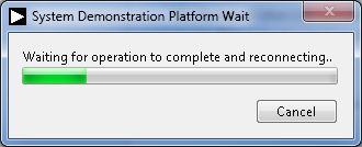
- Click the <html><a href=“#1”><b>Connect/Reconnect Button</b></a></html>. A window with a progress bar will load.<html><br><br></html>
 <html><br><br></html>
 - Upon success, the <html><a href=“#12”><b>System Status String Indicator</b></a></html> will display Ready to Capture Data<html><a id=“capture”><br></a></html>
Capturing Data
- <html><a href=“#usb”><b>Establish a USB Connection Link</b></a></html>.
- Click the <html><a href=“#5”><b>Input Channel Drop-Down Menu</b></a></html> to select the channel to convert
- Click the <html><a href=“#6”><b>Input Range Drop-Down Menu</b></a></html> to select the range of the analog input voltage.<html><br><br></html>
Changing this control will change the <html><a href=“#8”><b>AD8475 Gain Indicator</b></a></html>. Please ensure that JP3 and JP4 on the EVAL-CN0251-SDPZ (CN-0251 Board) are populated to reflect the gain displayed by the <html><a href=“#8”><b>AD8475 Gain Indicator</b></a></html>.
- Input the number of samples to capture into the <html><a href=“#9”><b>Samples to Capture Control</b></a></html>
- Click the <html><a href=“#2”><b>Capture Data Button</b></a></html> and wait until acquisition is complete.<html><br><br></html>

Changing the Display Units
- Click the <html><a href=“#10”><b>Display Unit Drop-Down Menu</b></a> to select the units to display</html>.
Saving Data to a Spreadsheet File
- <html><a href=“#usb”><b>Establish a USB Connection Link</b></a></html>.
- <html><a href=“#capture”><b>Capture Data</b></a></html>.
- Click the <html><a href=“#3”><b>Save Data Button</b></a></html>.
- Browse to the directory location where the spreadsheet file is to be saved.
- Name the file.
- Click the OK Button.
<html><br></html>The software saves the spreadsheet file as ASCII text with columns separated by tabs.
resources/eval/user-guides/circuits-from-the-lab/cn0251.1364852263.txt.gz · Last modified: 01 Apr 2013 23:37 by James Fitzgerald