


This version (30 Jul 2021 07:24) was approved by Victor Calinao, Jr.The Previously approved version (03 Jan 2021 21:55) is available.
Table of Contents
CN0240 Evaluation Board Guide
Overview
CN0240 is a circuit that monitors bidirectional current from sources with dc voltages of up to ±270 V with less than 1% linearity error. The load current passes through a shunt resistor, which is external to the circuit. The shunt resistor value is chosen so that the shunt voltage is approximately 100 mV at maximum load current.
AD629 is a difference amplifier with a very high input, common-mode voltage range. It is a precision device that accurately measures and buffers (G = 1) a small differential input voltage and rejects large positive common-mode voltages up to 270 V. The output of AD629 is then amplified by a factor of 100 through the dual, precision rail-to-rail output operational amplifier AD8622.
AD8475 is a fully differential, attenuating amplifier with integrated precision gain resistors. This funnel amplifier attenuates the signal (G = 0.4), converts it from single-ended to differential, and level shifts the signal to satisfy the analog input voltage range of the AD7170, a very low power 12-bit sigma-delta ADC. The measurement result from the AD7170 is provided as a digital code utilizing a simple 2-wire, SPI-compatible serial interface.
ADuM5402 is a quad channel isolator that provides galvanic isolation for the circuit. This is not only for protection but to isolate the downstream circuitry from the high common-mode voltage. In addition to isolating the output data, the digital isolator can also supply isolated +5 V for the circuit. The reference voltages for the circuit is supplied by the ADR435 precision XFET® reference. It features low noise, high accuracy, and low temperature drift performance.
The EVAL-CN0240-SDPZ Board connects to ADI’s System Demonstration Platform (SDP) and is powered by a +6 V supply or +6 V “wall wart”.

Required Equipment
- EVAL-SDP-CB1Z Controller Board (SDP-B Board)
- Power Supply
- 6 V @ 1 A or 6 V “Wall wart”
- Dual Power Supply
- +15 V and -15 V @ 10 mA
- PC with the following Minimum Requirements
- Windows 7 (32-bit), Windows Vista (32-bit) or Windows XP
- USB interface
- Shunt resistor with maximum voltage of 100 mV at the maximum load current
- Source voltage and electronic load
General Setup
Block assignments

- The EVAL-CN0240-SDPZ (CN-0240 Board) connects to the EVAL-SDP-CB1Z (SDP-B Board) via the 120-Pin connector
- The EVAL-SDP-CB1Z (SDP-B Board) connects to the PC via the USB cable.
- Terminal block J1 is the SDP connector
- Terminal block J2 is the +6 V barrel connector for wall wart supply input
- Terminal block J3 is the 6 V DC power supply
- Terminal block J4 is the high voltage input terminals
- Rshunt and load will be connected across these input terminals as indicated in test setup below
- Terminal block J5 is the input terminal for the dc supplies +15 V and -15 V
- Terminal block J6 is the test point for SPI data lines
High voltage! This circuit may contain lethal voltages. Do not operate, evaluate, or test this circuit, or board assembly, unless you are a trained professional, who is qualified to handle high voltage circuitry. Before applying power, you must be familiar with the circuitry and all required precautions for working with high voltage circuits.
Test setup
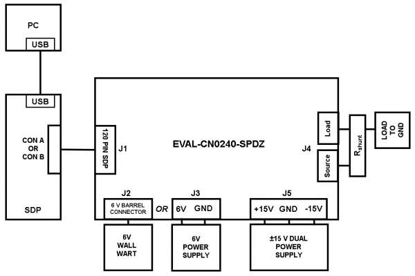
- Connect the 120-pin connector on the EVAL-CN0240-SDPZ Evaluation Board to the connector marked “CON A” on the EVAL-SDP-CB1Z evaluation (SDP) board
- Connect a shunt resistor across the J4 input terminals with a load to ground as indicated in figure above
- With power to the supply off, connect a +6 V power supply to the pins marked “+6V” and “GND” on the board
- If available, a +6 V “wall wart” can be connected to the barrel connector on the board and used in place of the +6 V power supply
- Connect the USB cable supplied with the SDP board to the USB port on the PC
- Apply power to the +6 V supply (or “wall wart”) connected to EVAL-CN0240-SDPZ Evaluation Board
- Launch the evaluation software
- Connect the USB cable from the PC to the USB mini connector on the SDP board
Connect the system ground and the PCB isolated ground to guarantee correct voltage levels and operation. Test point 31 and test point 32 give access to the GND_ISO required to properly make this connection.
Installing the Evaluation Software
- Extract the file CN0240_Evaluation_Software.zip and open the file setup.exe.
NOTE: It is recommended that you install the CN0240 Evaluation Software to the default directory path C:\Program Files (x86)\Analog Devices\CN0240\ and all National Instruments products to C:\Program Files\National Instruments\

- Click Next to view the installation review page

- Click Next to start the installation

- Upon completion of the installation of the CN-0240 Evaluation Software, the installer for the ADI SDP Drivers will execute.
NOTE: It is recommended that you close all other applications before clicking “Next”. This will make it possible to update relevant system files without having to reboot your computer.

- Press “Next” to set the installation location for the SDP Drivers.
It is recommended that you install the drivers to the default directory path
C:\Program Files\Analog Devices\SDP\Drivers

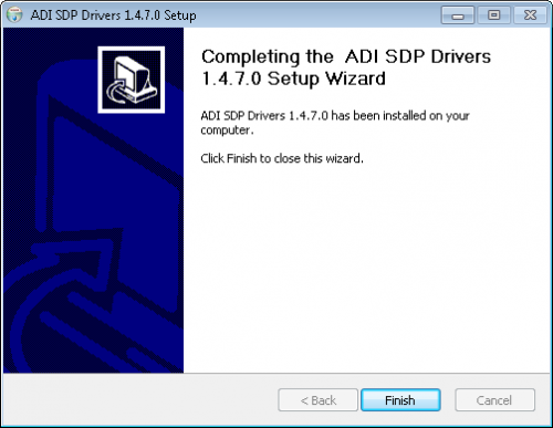
- Press “Install” to install the SDP Drivers and complete the installation of all software. Click “Finish” when done.
Using the Evaluation Software
Main Window

- Connect Button - Starts the connection between the CN0240 Evaluation Board and SDP-B Controller Board.
- Disconnect Button - Ends the connection between the CN0240 Evaluation Board and SDP-B Controller Board
- Data Acquisition Controls

- Select SDP Connector - Selects which 120-pin connection of the SDP-B Board to use
- Shunt voltage - Shunt voltage measurement from shunt resistor
- Sample Data - Start acquisition of measurement data
- Remove Data Point - Remove a data point from samples
- Calculate errors - Calculate conversion errors in ADC
- Save Data - Save measurement data to file
- Clear Data - Clear all data collected from the chart history
- Sample Data Graph Tab - Shows the XY plot of ADC code and output error (%) with respect to the shunt voltage

- Plot Options - Edit plot display and options like interpolation and color of output waveform
- Configure Tab

- SDP Connector - Selects which 120-pin connection of the SDP-B Board to use
- Flash LED - Flashes the LED on the SDP controller board
- Read Firmware - Reads the firmware of CN0240 Evaluation Board
- Quit Button - Closes the evaluation software
Running the System
- Open the CN0240.exe application from the default installation location
- Set the correct connector and click the Connect Button
- Upon successful connection, set the desired input signal parameters such as shunt voltage
- Start and control data acquisition through the data acquisition control buttons
- Output data will be shown in the graph. Edit graph through plot options and check boxes provided
- Click Disconnect if finished
- Click Quit to exit the program
More Information and Useful Links
Schematic, PCB Layout, Bill of Materials
EVAL-CN0240-SDPZ Design & Integration Files
- Schematics
- PCB Layout
- Bill of Materials
- PADS project
Registration
Receive software update notifications, documentation updates, view the latest videos, and more when you register your hardware. Register to receive all these great benefits and more!
End of Document
resources/eval/user-guides/circuits-from-the-lab/cn0240.txt · Last modified: 30 Jul 2021 07:24 by Victor Calinao, Jr