


This version (30 Jul 2021 07:16) was approved by Victor Calinao, Jr.The Previously approved version (28 Jan 2021 23:43) is available.
Table of Contents
Tilt Measurement Using a Dual Axis Accelerometer (CN0189)
Overview
The ADXL203 is a polysilicon surface micromachined sensor and signal conditioning circuit. Acceleration in the X or Y axis will produce a corresponding output voltage on the XOUT or YOUT output pins of the device. The X axis and Y axis are perpendicular to one another.The AD8608 quad op amp buffers, attenuates, and level shifts the ADXL203 outputs so they are at the proper levels to drive the inputs of the The AD7887. The AD7887 is configurable for either dual or single channel operation via the on-chip control register. In this application it is configured for dual channel mode, allowing the user to monitor both outputs of the ADXL203, thereby providing a more accurate and complete solution.
General Setup
- EVAL-CN0189-SDPZ Evaluation board.
- One SDP Controller board:
- EVAL-SDP-CS1Z SDP Evaluation board
- EVAL-SDP-CB1Z SDP Evaluation board
- 1 Six Volt DC Wall Wart ( EVAL-CFTL-6V-PWRZ)
- 1 USB Type-A plug to USB Mini-B plug cable


Minimum PC/System Requirements
- One PC with the following
- Windows XP SP2, Windows Vista or Windows 7 Business/Enterprise/Ultimate editions
- Intel Pentium processor (x86 compatible), 1GHz or faster
- 512 MB RAM and 2 GB available hard disk space
- .NET 3.5 Framework
How to Install the Evaluation Software
- Extract the files within the file CN0189 SDP Eval Software.zip and open the file setup.exe. It is recommended that you install the CN0189 SDP Evaluation Software to the default directory path C:\Program Files\Analog Devices\CN0189\ and all National Instruments products to C:\Program Files\National Instruments\

- Press “Next”.

- Press “Next”.
- Upon completion of the installation of the CN0189 SDP Eval Software, the installer for the ADI SDP Drivers will execute. Follow the on-screen prompts to install the drivers. It is recommended that you close all other applications before clicking “Next”. This will make it possible to update relevant system files without having to reboot your computer.

- Press “Next”.
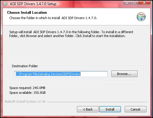
- It is recommended that you install the drivers to the default directory path C:\Program Files\Analog Devices\SDP\Drivers\
- Press “Next” to install the Drivers and complete the installation of all software necessary to evaluate the EVAL-CN0189-SDPZ


Step by Step Instruction for Connecting the Hardware
- Connect the EVAL-SDP-CS1Z and the EVAL-CN0189-SDPZ PCB’s using the 120 pin male and female connectors found on the respective boards.


- Plug in the DC barrel jack to connector J3 of the EVAL-CN0189-SDPZ and the mini end of the USB cable into connector J2 of the EVAL-SDP-CS1Z. And connect the other end of the USB cable into the Laptop or PC.


Opening and Enabling the Evaluation Software
- Launch the executable found at C:\Program Files\Analog Devices\CN0189 and press the “Connect“ button.

Step by Step Instruction to Using the Evaluation Software
- The following is a list of all available software controls, grouped according to their location in the software:
- System Controls
- Connect – This button configures the AD7887 by writing to the necessary registers.
- Disconnect – This button will disconnect the EVAL-CN0189-SDPZ board.
- Connector A - This menu allows the user to select which connector of the SDP board is being utilized.
- Conversion Mode Controls -
- Continuous Conversion Mode
- This control brings the user to the Demonstration Tab and locks out unnecessary tabs.
- This control displays/hides the necessary controls in the Data Acquisition Controls Tab.
- Data Acquisition Controls
- Click to Begin Continuous Sampling - This control starts the demonstration mode which measures the angle the PCB makes with the gravity vector and displays it.
- Single Sample
- This control brings the user to the Sample Data tab and locks out unnecessary tabs.
- This control displays/hides the necessary controls in the Data Acquisition Controls tab.
- Data Acquisition Controls
- Input Angle - Having set the PCB at a specific angle, this control allows the user to input that angle and to compare the ADC result with the actual angle.
- Single Sample - This control instructs the ADC to sample and convert one acceleration reading from each axis.
- Clear Data - This control clears the X-Y plot.
- Remove Data Point - This control removes the last data point from the X-Y plot.
- Save Data - This control prompts and allows the user to save their data to a text file.
Step by Step Instruction to Calibrate the Accelerometer
- Select Single Sample in the Conversion Mode Controls. Calibration can only be performed in the Single Sample mode.
- Navigate to the Calibrate tab.
- To manually enter or change calibration coefficients, press the Manual Coefficient Input button and enter the appropriate offset and sensitivity values for each axis (in g's).

- To perform a four point calibration, press the Four Point Calibration button.
- Orient the PCB as displayed in the image below.

- Press Sample Data while rotating the PCB to find the largest output voltage for the X-axis. This voltage corresponds to the +1g value for the X-axis.
- Orient the PCB as displayed in the image below.

- Press Sample Data while rotating the PCB to find the smallest output voltage for the X-axis. This voltage corresponds to the -1g value for the X-axis.
- Orient the PCB as displayed in the image below.

- Press Sample Data while rotating the PCB to find the largest output voltage for the Y-axis. This voltage corresponds to the +1g value for the Y-axis.
- Orient the PCB as displayed in the image below.

- Press Sample Data while rotating the PCB to find the smallest output voltage for the Y-axis. This voltage corresponds to the -1g value for the Y-axis.
- Press Calibrate to calculate the offset and sensitivity values for each axis.
- Now any further calculations or conversions performed anywhere in the software (Demonstration tab or Sampled Data tab) will utilize the offset and sensitivity values calculated here.


Registration
Receive software update notifications, documentation updates, view the latest videos, and more when you register your hardware. Register to receive all these great benefits and more!
End of document
resources/eval/user-guides/circuits-from-the-lab/cn0189.txt · Last modified: 30 Jul 2021 07:15 by Victor Calinao, Jr