


This version is outdated by a newer approved version. This version (03 Jan 2021 22:00) was approved by Robin Getz.The Previously approved version (04 Dec 2017 10:50) is available.
This version (03 Jan 2021 22:00) was approved by Robin Getz.The Previously approved version (04 Dec 2017 10:50) is available.This is an old revision of the document!
Table of Contents
CN0188 Evaluation Board Guide
Overview
CN0188 is a circuit that monitors current in individual channels of −48 V to better than 1% accuracy. The load current passes through a shunt resistor, which is external to the circuit. The shunt resistor value is chosen so that the shunt voltage is approximately 50 mV at maximum load current. The entire circuit operates on a single +3.3 V supply.
The AD7171 is a very low power, 16-bit, analog-to-digital converter (ADC). It contains a precision, 16-bit, Σ-Δ ADC and an on-chip oscillator. The measurement result from AD7171 is provided as a digital code utilizing a simple 2-wire, SPI-compatible serial interface. Optional galvanic isolation is provided by the ADUM5402 quad channel isolator. In addition to isolating the output data, the digital isolator can also supply isolated +3.3 V for the circuit.
The ADA4051-2 is a CMOS, micropower, zerodrift operational amplifier utilizing an innovative chopping technique. This amplifier feature rail-to-rail input/output swing and extremely low offset voltage while operating from a 1.8 V to 5.5 V power supply.
The ADR381 is precision 2.500 V band gap voltage reference featuring high accuracy, high stability, and low power consumption in a tiny footprint. It is a micropower, low dropout voltage (LDV) device that provides a stable output voltage from supplies as low as 300 mV above the output voltage.
The EVAL-CN0188-SDPZ Board connects to ADI’s System Demonstration Platform (SDP) and is powered by a +6 V supply or +6 V “wall wart”.

Required Equipment
- EVAL-SDP-CB1Z Controller Board (SDP-B Board)
- Power Supply
- 6 V or 6 V Wall wart
- PC with the following Minimum Requirements
- Windows 7 (32-bit), Windows Vista (32-bit) or Windows XP
- USB interface
- Shunt resistor with maximum voltage of 50 mV at the maximum load current
- Electronic load
General Setup
Block assignments

- The EVAL-CN0188-SDPZ (CN-0188 Board) connects to the EVAL-SDP-CB1Z (SDP-B Board) via the 120-Pin connector
- The EVAL-SDP-CB1Z (SDP-B Board) connects to the PC via the USB cable.
- Terminal block J2 is the +6 V barrel connector for wall wart supply input
- Terminal block J3 is the test point for 6 V DC output
- Terminal block J4 contains the input terminals for Rshunt and load to ground
Test setup

- Connect the 120-pin connector on the EVAL-CN0188-SDPZ Evaluation Board to the connector marked “CON A” on the EVAL-SDP-CB1Z evaluation (SDP) board
- Connect a shunt resistor across the input terminals with a load to ground as indicated in figure above
- With power to the supply off, connect a +6 V power supply to the pins marked “+6V” and “GND” on the board
- If available, a +6 V “wall wart” can be connected to the barrel connector on the board and used in place of the +6 V power supply
- Connect the USB cable supplied with the SDP board to the USB port on the PC
- Apply power to the +6 V supply (or “wall wart”) connected to EVAL-CN0188-SDPZ Evaluation Board
- Launch the evaluation software
- Connect the USB cable from the PC to the USB mini connector on the SDP board
Connect the system ground and the PCB isolated ground to guarantee correct voltage levels and operation. Test point 31 and test point 32 give access to the GND_ISO required to properly make this connection.
Installing the Evaluation Software
- Extract the file CN0188_Evaluation_Software.zip and open the file setup.exe.
NOTE: It is recommended that you install the CN0188 Evaluation Software to the default directory path C:\Program Files (x86)\Analog Devices\CN0188\ and all National Instruments products to C:\Program Files\National Instruments\

- Click Next to view the installation review page

- Click Next to start the installation

- Upon completion of the installation of the CN-0188 Evaluation Software, the installer for the ADI SDP Drivers will execute.
NOTE: It is recommended that you close all other applications before clicking “Next”. This will make it possible to update relevant system files without having to reboot your computer.

- Press “Next” to set the installation location for the SDP Drivers.
It is recommended that you install the drivers to the default directory path
C:\Program Files\Analog Devices\SDP\Drivers

- Press “Install” to install the SDP Drivers and complete the installation of all software. Click “Finish” when done.

Using the Evaluation Software
Test Setup Tab
Main Window

- Connect Button - Starts the connection between the CN0188 Evaluation Board and SDP-B Controller Board.
- Disconnect Button - Ends the connection between the CN0188 Evaluation Board and SDP-B Controller Board
- Select SDP Connector - Selects which 120-pin connection of the SDP-B Board to use
- Shunt Voltage Input - Determines input shunt voltage level in millivolts
- Temperature - Temperature level test conditions of input signal
- Data Acquisition Controls
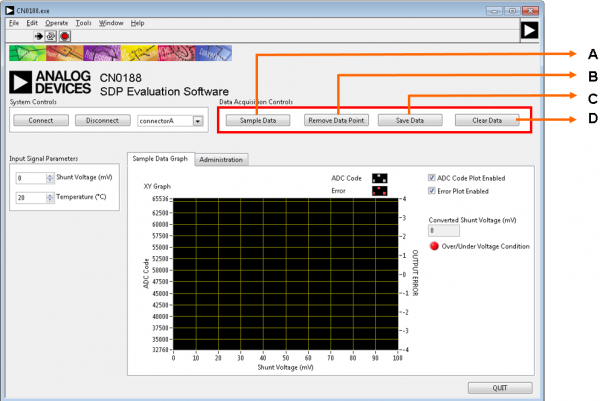
- Sample Data - Start acquisition of measurement data
- Remove Data Point - Remove a data point from samples
- Save Data - Save measurement data to file
- Clear Data - Clear the current measurement data
- Sample Data Graph Tab - Shows the XY plot of ADC code and output error (%) with respect to the shunt voltage

- ADC Code Plot Enable - Show or hide the ADC Code plot
- Error Plot Enable - Show or hide the Error plot
- Converted Shunt Voltage - Shunt voltage value from the ADC
- Over/Under Voltage Indicator - Indicates over or under voltage conditions
- Plot Options - Edit plot display and options like interpolation and color of output waveform
- Administration Tab

- Flash LED - Flashes the LED on the SDP controller board
- Read Firmware - Reads the firmware of CN0240 Evaluation Board
- Quit Button - Closes the evaluation software
Running the System
- Open the CN0188.exe application from the default installation location
- Set the correct connector and click the Connect Button
- Upon successful connection, set the desired input signal parameters such as shunt voltage and temperature
- Start and control data acquisition through the data acquisition control buttons
- Output data will be shown in the graph. Edit graph through plot options and check boxes provided
- Click Disconnect if finished
- Click Quit to exit the program
More Information and Useful Links
Schematic, PCB Layout, Bill of Materials
EVAL-CN0188-SDPZ Design & Integration Files
- Schematics
- PCB Layout
- Bill of Materials
- PADS project
End of Document
resources/eval/user-guides/circuits-from-the-lab/cn0188.1609707356.txt.gz · Last modified: 03 Jan 2021 21:55 by Robin Getz