


This version (30 Jul 2021 07:14) was approved by Victor Calinao, Jr.The Previously approved version (03 Jan 2021 21:55) is available.
Table of Contents
CN0187 Crest Factor, Peak, and RMS RF Power Measurement Circuit Optimized for High Speed, Low Power, and Single 3.3 V Supply
Overview
The circuit measures peak and rms power at any RF frequency from 450 MHz to 6 GHz over a range of approximately 45 dB. The measurement results are converted to differential signals in order to eliminate noise and are provided as digital codes at the output of a 12-bit SAR ADC with serial interface and integrated reference. A simple twopoint calibration is performed in the digital domain.

General Setup
- EVAL-CN0187-SDPZ Evaluation Board
- EVAL-SDP-CB1Z Evaluation Board
-
- (supplied with provided CD in kit)
- Power supply: +6 V, or +6 V “wall wart”
- USB Type-A plug to USB Mini-B plug cable
- RF signal source (>6GHz)
- Coaxial RF cable with SMA connectors
Minimum PC/System Requirements
- One PC with the following
- Windows XP SP2, Windows Vista or Windows 7 Business/Enterprise/Ultimate editions
- Intel Pentium processor (x86 compatible), 1GHz or faster
- 512 MB RAM and 2 GB available hard disk space
- .NET 3.5 Framework
How to Install the Evaluation Software
- Extract the file CN0187 Eval Software.zip and open the file setup.exe.
NOTE: It is recommended that you install the CN0187 Evaluation Software to the default directory path C:\Program Files\Analog Devices\CN0187\ and all National Instruments products to C:\Program Files\National Instruments\

- Click Next to view the installation review page

- Click Next to start the installation

- Upon completion of the installation of the CN0187 Evaluation Software, the installer for the ADI SDP Drivers will execute.
NOTE: It is recommended that you close all other applications before clicking “Next”. This will make it possible to update relevant system files without having to reboot your computer.

- Press “Next” to set the installation location for the SDP Drivers.
\\It is recommended that you install the drivers to the default directory path
C:\Program Files\Analog Devices\SDP\Drivers

- Press “Next” to install the SDP Drivers and complete the installation of all software. Click “Finish” when done.

Connecting the Hardware

- Connect the 120-pin connector on the EVAL-CN0187-SDPZ circuit board to the connector marked “CON A” on the EVAL-SDP-CB1Z evaluation (SDP) board. Nylon hardware should be used to firmly secure the two boards, using the holes provided at the ends of the 120-pin connectors as depicted in the image below.
- Using an appropriate RF cable, connect the RF signal source to the EVAL-CN0187-SDPZ board via the SMA RF input connector.
- With power to the supply off, connect a +6 V power supply to the pins marked “+6 V” and “GND” on the board. If available, a +6 V “wall wart” can be connected to the barrel jack connector on the board and used in place of the +6 V power supply.
- Connect the USB cable, supplied along with the EVAL-SDP-CB1Z evaluation board, from the SDP board to the USB port on the PC.
Using the Evaluation Software
The following software section will help describe the steps you will need to go through when using the hardware and software together. There are some nationalizations and calibrations which must be done, and then some commands and instructions on how to use the software. Please read carefully to completely understand how to use the demo.
Below are the list of available software controls grouped according to their location in the
software GUI:

Calibration

Calibration procedure needs to be done for every change in frequency.

- Input
- Input Power (dBm)
- value of a known power level input in dBm
- Frequency (MHz)
- value of a known frequency level input in MHz
- Acquire Data
- acquire the data from the provided input in the power and frequency level
- Remove List
- remove the last data that was provided in the input power and frequency level
- Calibrate Data
- execute the calibration process
- Clear Calibration
- clear the value from the previous settings
- Save Calibration File
- save the current value provided at the input for power and frequency level
- Load Calibration File
- load the desired saved calibrated settings
- Output
- Vrms (V)
- display the calculated RMS voltage output from the known power level and frequency input
- Peak (V)
- display the calculated peak voltage output from the known power level and frequency input
- Calibration Complete
- indicate a complete calibration process
Measure Input Power
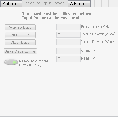
The board must be calibrated before Input Power can be measured
- List of Input Buttons
- Acquire Data
- acquired data from the device
- Remove List
- remove the last data read
- Clear Data
- set all the values from the display to 0
- Save Data to File
- save the values displayed
- Peak-Hold Mode (Active Low)
- hold the last value read from acquiring the data
- Output
- Frequency (MHz)
- display the acquired frequency in MHz
- Input Power (dBm)
- display the acquired input power in dBm
- Input Power (Vrms)
- display the acquired input RMS voltage value
- Vrms (V)
- display the calculated RMS voltage value
- Peak (V)
- display the calculated peak voltage value
Advanced

Note: Do not modify these values unless you need to
- Sclk (Hz)
- set the SPI clock reference
- /CS (Hz)
- set the Chip select clock settings
- Sample Size
- set the sample size
Graphical Output


- dBm - output displayed in dBm
- Vrms- output displayed in Vrms


Crest factor is the peak amplitude of the waveform divided by the RMS value of the waveform
Schematics, PCB Layout, Bill of Materials
- Schematics (PDF)
- Bill of Materials(Excel)
- Layout Gerbers(ZIP)
- Assembly Drawing(PDF)
Registration
Receive software update notifications, documentation updates, view the latest videos, and more when you register your hardware. Register to receive all these great benefits and more!
End of Document
resources/eval/user-guides/circuits-from-the-lab/cn0187.txt · Last modified: 30 Jul 2021 07:14 by Victor Calinao, Jr