


The most recent version of this page is a draft. This version is outdated by a newer approved version.This version (25 Oct 2017 09:07) is a draft.
Approvals: 0/1
This version is outdated by a newer approved version.This version (25 Oct 2017 09:07) is a draft.Approvals: 0/1
This is an old revision of the document!
Table of Contents
CN0178 Evaluation Board Guide
Overview
CN0178 is a circuit that measures the rms signal strength of RF signals with varying crest factors (peak-to-average ratio) over a dynamic range of approximately 65 dB and operates at frequencies from 50 MHz up to 9 GHz using the ADL5902 TruPwr™ detector. The measurement result is provided as serial data at the output of a 12-bit ADC. A simple 4-point system calibration at ambient temperature is performed in the digital domain.
The ADL5902 provides a solution in a variety of high frequency systems requiring an accurate measurement of signal power. It can operate from 50 MHz to 9 GHz and can accept inputs from −62 dBm to at least +3 dBm with large crest factors, such as GSM, CDMA, W-CDMA, TD-SCDMA, WiMAX, and LTE modulated signals.
The AD7466 12-bit, high speed, low power, successive approximation analog-to-digital converters (ADC). It operates from a single 1.6 V to 3.6 V power supply and feature throughput rates up to 200 kSPS with low power dissipation. The parts contain a low noise, wide bandwidth track-and-hold amplifier, which can handle input frequencies in excess of 3 MHz.
The EVAL-CN0178-SDPZ board connects to ADI’s System Demonstration Platform (SDP) and is powered by a +6 V supply or +6 V “wall wart”.

Required Equipment
- EVAL-SDP-CB1Z Controller Board (SDP-B Board)
- Power Supply
- 6 V or 6 V Wall wart
- PC with the following Minimum Requirements
- Windows 7 (32-bit), Windows Vista (32-bit) or Windows XP
- USB interface
- RF signal source (Optional)
- Rohde & Schwarz SMT-03 RF signal source
- Coaxial RF cable with SMA connectors
General Setup
Block assignments

- The EVAL-CN0178-SDPZ (CN-0178 Board) connects to the EVAL-SDP-CB1Z (SDP-B Board) via the 120-Pin connector
- The EVAL-SDP-CB1Z (SDP-B Board) connects to the PC via the USB cable.
- Terminal block J1 is the +6 V test point
- Terminal block J2 is the +6 V power supply jack
- Terminal block J3 is the SMA connector for RF input
Do not connect the USB cable to the Mini-USB connector on the SDP board before turning on the dc power supply for the EVAL-CN0178-SDPZ.
Installing the Evaluation Software
- Extract the file CN0178_Evaluation_Software.zip and open the file setup.exe.
NOTE: It is recommended that you install the CN0178 Evaluation Software to the default directory path C:\Program Files (x86)\Analog Devices\CN0178\ and all National Instruments products to C:\Program Files\National Instruments\

- Click Next to view the installation review page
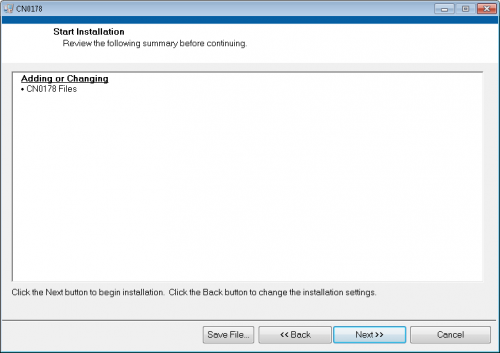
- Click Next to start the installation

- Upon completion of the installation of the CN-0178 Evaluation Software, the installer for the ADI SDP Drivers will execute.
NOTE: It is recommended that you close all other applications before clicking “Next”. This will make it possible to update relevant system files without having to reboot your computer.

- Press “Next” to set the installation location for the SDP Drivers.
It is recommended that you install the drivers to the default directory path
C:\Program Files\Analog Devices\SDP\Drivers

- Press “Install” to install the SDP Drivers and complete the installation of all software. Click “Finish” when done.

Using the Evaluation Software
Test Setup Tab

More Information and Useful Links
Schematic, PCB Layout, Bill of Materials
EVAL-CN0178-SDPZ Design & Integration Files
- Schematics
- PCB Layout
- Bill of Materials
- PADS project
End of Document
resources/eval/user-guides/circuits-from-the-lab/cn0178.1508915268.txt.gz · Last modified: 25 Oct 2017 09:07 by Trisha Cabildo