


This version (18 Jul 2023 05:06) was approved by Angelo Nikko Catapang.The Previously approved version (18 Jul 2023 05:00) is available.
Table of Contents
CN-0326 Software User Guide
OVERVIEW
The circuit is a completely isolated low power pH sensor signal conditioner and digitizer with automatic temperature compensation for high accuracy. The circuit gives 0.5% accurate pH readings for pH values from 0 pH to 14 pH with greater than 14-bits of noise-free code resolution and is suitable for a variety of industrial applications such as chemical, food processing, water, and waste water analysis. This circuit supports a wide variety of pH sensors that have very high internal resistance that can range from 1 MΩ to several TGΩ. , and digital signal and power isolation provides immunity to noise and transient voltages often encountered in harsh industrial environments.
GENERAL SETUP
- EVAL-CN0326-PMDZ Evaluation Board
- EVAL-SDP-CB1Z Evaluation Board
- SDP-PMD-IB1Z Evaluation Board
-
- (supplied with provided CD in kit)
- +6V DC power supply
- USB Type-A plug to USB Mini-B plug cable
- pH probe with BNC connector
- RTD sensor with RCA connector
MINIMUM PC/SYSTEM REQUIREMENTS
- One PC with the following
- Windows XP SP2, Windows Vista or Windows 7 Business/Enterprise/Ultimate editions
- Intel Pentium processor (x86 compatible), 1GHz or faster
- 512 MB RAM and 2 GB available hard disk space
- .NET 3.5 Framework
HOW TO INSTALL THE EVALUATION SOFTWARE
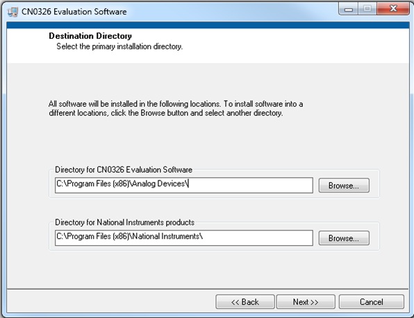
- Extract the file CN0326 Eval Software.zip and open the file setup.exe.
NOTE: It is recommended that you install the CN0326 Evaluation Software to the default directory path C:\Program Files\Analog Devices\CN0326\ and all National Instruments products to C:\Program Files\National Instruments\
- Click Next to view the installation review page

- Click Next to start the installation

- Upon completion of the installation of the CN0326 Evaluation Software, the installer for the ADI SDP Drivers will execute.
NOTE: It is recommended that you close all other applications before clicking “Next”. This will make it possible to update relevant system files without having to reboot your computer.

- Press “Next” to set the installation location for the SDP Drivers.
It is recommended that you install the drivers to the default directory path
C:\Program Files\Analog Devices\SDP\Drivers

- Press “Next” to install the SDP Drivers and complete the installation of all software. Click “Finish” when done.


STEP BY STEP INSTRUCTION FOR CONNECTING THE HARDWARE

- Plug the mini end of the USB cable into connector J1 of the EVAL-SDP-CB1Z and connect the other end of the USB cable into the Laptop or PC.
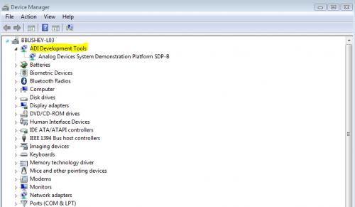
- Make sure that the computer installs the device drivers, and that you can see the ADI Development Tools in your computer's device manager.
- Remove the jumper across JP1 found on the SDP-PMD-IB1Z.
- Connect the 120-pin connector of the SDP-PMD-IB1Z circuit board to the connector marked “CON A” on the EVAL-SDP-CB1Z evaluation (SDP) board. Nylon hardware should be used to firmly secure the two boards, using the holes provided at the ends of the 120-pin connectors.
- Connect the EVAL-CFTL-6V-PWRZ to J1 barrel jack of the SDP-PMD-IB1Z, and WAIT 10 SECONDS before continuing
- Connect the 12-pin right angle male pin header of EVAL-CN0326-PMDZ to the 12-pin right angle female pin header of SDP-PMD-IB1Z.
- Connect the pH probe in J1 of EVAL-CN0326-PMDZ.
- Connect the RTD sensor in P1 of EVAL-CN0326-PMDZ.
- Place the jumper across JP1 on the SDP-PMD-IB1Z and make sure it's positioned to +3.3V.
- Check again in the device manager to make sure the ADI Development Tools are still displaying. If yes, then you'll be able to proceed onto the evaluation software section. If you don't see ADI Development Tools, than you will have to start the hardware evaluation procedure over at step 1.

OPENING AND ENABLING THE EVALUATION SOFTWARE

- Launch the executable found at C:\Program Files\Analog Devices\CN0326 and press the “Connect” button.
- After pressing the “Connect” button, a prompt will appear informing the user that the SDP is now ready to acquire data and the rest of the buttons found in System Controls will be enabled.
- Press the “Run” button in order to start using the program.
STEP BY STEP INSTRUCTION USING THE EVALUATION SOFTWARE

- Below are the list of available software controls grouped according to their location in the software GUI:
- System Controls
- Connect – This button configures the AD7793 by writing to the necessary registers. A prompt will appear informing the user if the ADC was properly configured.
- Run – This button polls the data ready bit in the AD7793 status register. When this bit is set, LabVIEW reads the data registers and displays the pH reading and the temperature data on the chart found in the evaluation software.
- Save Data – This button saves all data displayed in the LabVIEW chart.
- Clear Data – This button clears all data displayed in the LabVIEW chart.
- Data Graph – This page contains a waveform chart visually displaying the pH readings and the temperature readings taken after clicking the Run button.
- Calibration Settings – This page contains the controls necessary to calibrate the entire pH measurement system using a two-point linear interpolation.
- Two Point Calibration – This button will calculate the calibration coefficients based on two data points gathered on the Sampled Data page.
- Voltage Offset Calibration – Removes the offset introduce by the pH probe and by the System after clicking the Remove Offset Voltage button.
- Buffer Solution 1 – This gives the customer an option to choose the source of the list of table of the temperature coefficient for buffer solution 1 that will be used for calibration. This option also set the first point for calibration after clicking the Calibration Point 1.
- NIST Standard Buffer Solution – allows the customer to choose the predefined list of table for the buffer solution traceable by the NIST.
- Custom Buffer Solution - allows the user an option to choose a table that gives the temperature coefficient of the buffer solution to be used for calibration.
- Buffer Solution 2 – This gives the customer an option to choose the source of the list of table of the temperature coefficient for buffer solution 2 that will be used for calibration. This option also set the second point for calibration after clicking the Calibration Point 2.
- NIST Standard Buffer Solution – allows the customer to choose the predefined list of table for the buffer solution traceable by the NIST.
- Custom Buffer Solution - allows the user an option to choose a table that gives the temperature coefficient of the buffer solution to be used for calibration.
- Measured Results –Display the result for pH reading, the corresponding voltage for the pH reading and the slope expressed in mV/pH.
- Continuous Temperature Compensation – This allows the user to enable or disable continuous temperature compensation for pH reading.
- Data Rate – This allows the user to modify the rate of data acquisition which changes instantly by clicking Refresh Rate button.
- RTD Value – This allows the user to use other RTD value according to their requirements.
- Save/Recall Calibration Settings – this allows the user to save setup by clicking the Save button or recall the calibration setup formatted in a text file.
- To save the calibration settings, click Save button then a choose the desired location and provide a the file with a text file(.txt) extension to create new file or click to over write an existing file with a .txt extension.
- To recall the calibration setting, click the folder to browse for the location of the text file that contains the calibration settings and click Load to change the settings indicated in the file that was loaded.
- SDP Board Firmware Revision – provides details on the firmware version of the Blackfin used by the SDP board.
- Note: Example of a format for the calibration setup can be found in the Design Support Package with a folder name Calibration Text Format
CALIBRATION
Pre-Calibration Note:
- A minimum of two buffer solution of different pH values have to be selected.
- One of these buffer solutions should be pH 7 for the zero point compensation.
- The second buffer solution should have a pH value which lies as near as possible to the anticipated measuring range.
- The third buffer solution will be needed if the expected measuring range covers the acidity and alkalinity range where in the pH value of the second and third buffer solution should fall under the acid region and alkaline region respectively.
- The value of the chosen buffer solution should at least differ by 2 pH units.
- The electrode assembly of a pH probe has to stay in the buffer solution for a short time till the indication of the pH meter become stable.
This section explains the steps required to properly calibrate the EVAL-CN0326-PMDZ pH measurement system.
- Step 1
- Immersed the pH probe along with the temperature sensor into the buffer solution with pH value of 7 for zero point compensation.
- Click Remove Offset Voltage button once the pH voltage reading becomes stable.
- Step 2
- After rinsing the electrode assembly with deionized or distilled water, immersed the pH probe with the temperature sensor into the second chosen buffer solution.
- Select the source of the buffer solution temperature coefficient table for compensation.
- When choosing the predefined table preprogrammed in this software, choose the pH value that corresponds to the buffer solution that will be used to define the second point.
- When choosing the custom buffer solution table, navigate through the panel that contains the file that will be used for temperature compensation. (Note: a sample format of a table can be found in CN0326 Design Support Package with a folder name NIST Buffer Solution Table Format)
- After choosing the source of the buffer solution temperature coefficient table, click Calibration Point 1 button to set the second point of calibration.
- Step 3
- After rinsing the electrode assembly with deionized or distilled water, immersed the pH probe with the temperature sensor into the third chosen buffer solution.
- Select the source of the buffer solution temperature coefficient table for compensation.
- When choosing the predefined table preprogrammed in this software, choose the pH value that corresponds to the buffer solution that will be used to define the third point.
- When choosing the custom buffer solution table, navigate through the panel that contains the file that will be used for temperature compensation. (Note: a sample format of a table can be found in CN0326 Design Support Package with a folder name NIST Buffer Solution Table Format)
- After choosing the source of the buffer solution temperature coefficient table, click Calibration Point 2 button to set the third point of calibration.
Registration
Receive software update notifications, documentation updates, view the latest videos, and more when you register your hardware. Register to receive all these great benefits and more!
resources/eval/user-guides/circuits-from-the-lab/cn0326.txt · Last modified: 18 Jul 2023 05:02 by Angelo Nikko Catapang