


This version (29 Jul 2021 07:17) was approved by Harvey John De Chavez.The Previously approved version (09 Jan 2021 00:32) is available.
Table of Contents
CN0295: Flexible, 4 mA-to-20 mA Pressure Sensor Transmitter with Voltage or Current Drive
OVERVIEW
The circuit is a flexible current transmitter that converts the differential voltage output from a pressure sensor to a 4 mA-to-20 mA current output. The circuit is optimized for a wide variety of bridge-based voltage or current driven pressure sensors, utilizes only five active devices, and has a total unadjusted error of less than 1%. The power supply voltage can range from 7 V to 36 V depending on the component and sensor driver configuration. The input of the circuit is protected for ESD and voltages beyond the supply rail, making it ideal for industrial applications.

DEMO REQUIREMENTS
- EVAL-CN0295-EB1Z circuit evaluation board
- +7V to +24V power supply or equivalent power supply
- Precision power supply
- Agilent 3458A or equivalent Current meter
- Differential Pressure sensor or Equivalent Dual channel DC Signal Source
HARDWARE SETUP
Power Supply
- From +7V to +24V supply can be used to J2 for proper operation of the evaluation board
In order for the circuit to operate properly, the supply voltage, must be greater than 7 V in order to provide sufficient headroom.
Input Signal
Using Actual Sensor


- A differential output bridge type sensor should be attached to a 4 channel screw terminal block (J3) labeled with SUPPLYSNS on the PCB.
- A differential sensor gauge like from NXP which can be used for evaluation.
- Vsense is where the analog voltage output of the sensor is being taken for measurement. Pin polarity should be take into account.
- V/Iforce is the sensor excitation or is being supplied either from current or voltage source.
Pin polarity for Vsense and for V/Iforce should be take into consideration
Using Simulated input sensor
The following configuration can be used to simulate the sensor characteristic for evaluation purposes.
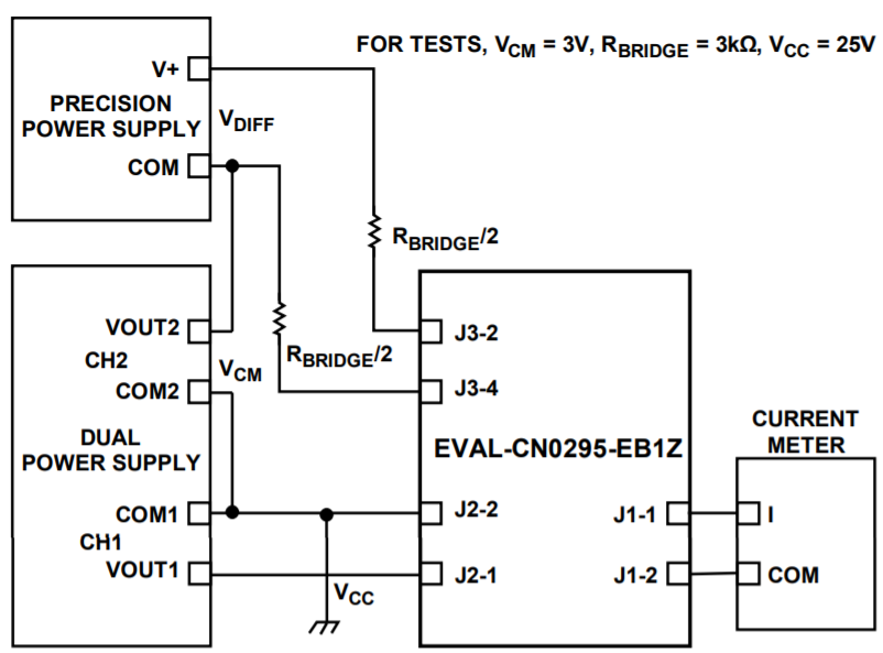
- A dual power supply can be used to power up the board from Vout1 and to generate a common-mode voltage of 2.5 V from Vout2 shown in the block diagram for test setup.
- A precision voltage source generates the 0 to 100 mV differential input voltage at the in-amp input, which then simulates the sensor output shown in the block diagram for test setup.
- 3 kΩ at R_bridge simulates the bridge type sensor impedance.

For lower than 5 kΩ bridge resistance, the drive voltage can be decreased down to 5 V using a buffer configuration by removing resistor R6.
Sensor Drive
The circuit can be switched to the current or voltage drive configuration by moving S1 to the position labeled on the PCB.

Voltage Drive Configuration
- In the voltage drive mode with VDRIVE = 10 V, the supply voltage VLOOP or system supply must be greater than 10.2 V
Current Drive Configuration
- In the current drive mode, the supply voltage VLOOP or system supply must be greater than 11.2 V in order to maintain sufficient headroom.
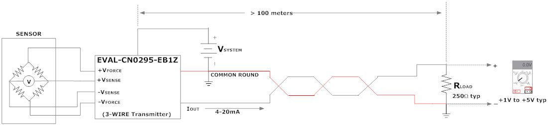
Current drive configuration can be used for four-wire ohm circuit configuration where in the main advantage of this configuration is that the voltage is measured directly across the load cell, neglecting the load effect of the lead wires for long distance measurements.
Both for voltage and current drive mode, the minimum loop supply voltage is dependent on the configuration of the drive circuit for the bridge.
Output Measurements
The output of the system can be measured in two ways, either through direct output current measurement or voltage output through the series resistor.

* Voltage Measurement
- Voltage output measurement is done across a series 250ohms resistor though screw type terminal block (P1).
It is important that the 2-pin male header (J1) be populated first before doing a voltage measurement across the terminal block (P1)

* Current Measurement
- Current output measurement is done by connecting the positive terminal of the current meter at one pin of the male header shunt terminal (J1) and the negative terminal of the meter connected to the other pin of the same male header shunt terminal.
The system has an onboard resistor load (R14) of 500ohms that can be de-soldered to replace with a desired resistor load value
SCHEMATICS, PCB LAYOUT, BILL OF MATERIALS
- Schematics (PDF)
- Bill of Materials(Excel)
- Layout Gerbers(ZIP)
- Assembly Drawing(PDF)
Registration
Receive software update notifications, documentation updates, view the latest videos, and more when you register your hardware. Register to receive all these great benefits and more!
End of Document
resources/eval/user-guides/circuits-from-the-lab/cn0295.txt · Last modified: 29 Jul 2021 07:17 by Harvey John De Chavez