


This version (30 Jul 2021 07:20) was approved by Victor Calinao, Jr.The Previously approved version (11 Feb 2021 16:15) is available.
Table of Contents
CN0203 Evaluation Board Guide
Overview
CN0203 is a full function, flexible, programmable analog output solution with only two analog components and meets most requirements for programmable logic controller (PLC) and distributed control system (DCS) applications. It provides all the typical current and voltage output ranges with 16-bit resolution and no missing codes, 0.05% linearity, and less than 0.1% output error. Furthermore, it also contains key features for industrial applications, such as on-chip output fault detection, CRC checking to prevent packet error (PEC), and flexible power-up options, making it an ideal choice for robust industrial control systems. No external precision resistors or calibration routines are needed to maintain consistent performance in mass production, thereby making it ideal for PLC or DCS modules.
The AD5750-1 are single-channel, low cost, precision voltage/current output drivers developed to meet the requirements of industrial process control applications. The voltage output range can be programmed for the standard output ranges for PLC and DCS applications: 0 V to 5 V, 0 V to 10 V, −5 V to +5 V, and −10 V to +10 V. A 20% overrange setting is also provided for the standard ranges, giving the following options: 0 V to 6 V, 0 V to 12 V, −6 V to +6 V, and −12 V to +12 V. The current output, which is provided on a separate pin, can be programmed for the ranges of 4 mA to 20 mA, 0 mA to 20 mA, −20 mA to +20 mA, 0 mA to 24 mA, and −24 mA to +24 mA. The unipolar ranges have a 2% overrange setting. The voltage and current output pins can be tied together to configure the end system as a single-channel output if desired.
The AD5660-1 is a single channel, low cost, low power, rail-torail voltage buffered output nanoDAC integrated with an onchip 1.25 V, 5 ppm/°C reference. The AD5660-1 incorporates a power-on reset circuit to ensure that the DAC output powers up to 0 V and remains there until a valid write command takes place. The output voltage range of the AD5660-1 is 0 V to 2.5 V, which matches the input range of the AD5750-1. In addition, the reference output voltage of the AD5660-1 is 1.25 V, which precisely matches the reference input requirement of the AD5750-1.
The CN0203 needs +15 V, -15 V and +6 V power supply inputs and thus, needs a triple output DC power supply. The board also connects to ADI's System Demonstration Platform (SDP).
Required Equipment
- ±25 V/1 A Triple Output DC Power Supply (Agilent E3631A)
- Optional Digital Multimeter for Verification (Agilent 34401A 6.5 Digital Multimeter)
- PC with USB interface
- Windows 7 or higher
General Setup
Block Assignments

- The EVAL-CN0203-SDPZ (CN0203 Board) connects to the EVAL-SDP-CB1Z (SDP-B Board) via the 120-Pin Connector (SDP-B CONN)
- The EVAL-SDP-CB1Z (SDP-B Board) connects to the PC via the USB cable
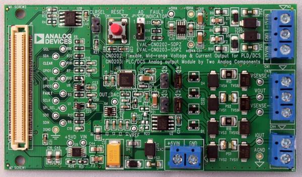
- Terminal block CN1 is the +/- 15 V power supply input
- Terminal block CN2 is the +6 V power supply input
- Terminal block CN3 is for the voltage output measurement
- Optionally if JP3 and JP4 are open, VSENSE+ and VSENSE- can be connected across a selected branch in the load circuit for feedback. VSENSE- should be within +/- 3.0 V of the GND
- Terminal block CN4 is for the current output measurement
Power on the (EVAL-CN0203-SDPZ) through the triple output power supply and the (SDP-B Board) through the PC SEPARATELY before connecting the two boards together.
Jumper Settings
See the table in the image below for the jumper settings. Values in red are the default settings for the EVAL-CN0203-SDPZ.

Installing the Evaluation Software
- Extract the file CN0203 Evaluation Software and open setup.exe
NOTE: It is recommended that you install the CN0203 Evaluation Software to the default directory path C:\Program Files (x86)\Analog Devices\CN0203\ and all National Instruments products to C:\Program Files\National Instruments\

- Press Next to view the National Instruments Software License Agreement

- Select the option which accepts the License Agreement and press Next to view the installation review page

- Press Next to start the installation

- Upon completion of the installation of the CN0203 Evaluation Software, the installer for the ADI SDP Drivers will execute
NOTE: It is recommended that you close all other applications before clicking “Next”. This will make it possible to update relevant system files without having to reboot your computer.

- Press “Next” to set the installation location for the SDP Drivers
It is recommended that you install the drivers to the default directory path
C:\Program Files\Analog Devices\SDP\Drivers

- Press “Next” to install the SDP Drivers. When prompted by Windows Security, just press Install

- Press Finish to complete the installation

Using the Evaluation Software
Main Window

- Title Bar (Highlighted Violet)
- Connect Button
- Starts the connection with the CN0203 Evaluation Board
- Disconnect Button
- Ends the connection with the CN0203 Evaluation Board
- System Configuration (Highlighted Orange)
- Connector
- Selects which 120-pin connection of the SDP-B Board to use
- SCLK (Hz)
- Sets the SPI clock frequency used by the evaluation board
- AD5750-1 Configuration (Highlighted Blue)
- JP1 Configuration
- Sets the SPI address of the AD5750-1 based on the position of JP1
- Range Select
- Sets the voltage/current output range
- Toggle CLEAR
- Sets the outputs to the zero/midscale voltage value or the minimum value of the selected current range
- AD5750-1 Error Indicator (Highlighted Yellow)
- Vout Fault
- There is a short circuit on the VOUT pin
- Iout Fault
- There is an open circuit on the IOUT pin
- Over Temp
- The AD5750-1 core temperature exceeds 150 °C
- PEC Error
- CRC-8 error checking detected an interface error
- Output Setting Highlighted Red
- Write AD5660-1
- Writes the hexadecimal value in the left field to the AD5660-1 output voltage
- Reset AD5750-1
- Resets the AD5750-1 to its power-on state
- Quit
- Exits the software application
Running the System
- Open the CN0203.exe application from the default installation location.
- Set the correct connector and SCLK settings for the board in the System Configuration section.
- Click the Connect Button
- Upon successful connection, select the desired range of output on the Range Select drop-down menu.
- Input a hex value equivalent of the desired output level in the Output Setting section.
- Click Write AD5660-1
- Click Disconnect Button if finished.
More Information and Useful Links
Schematic, PCB Layout, Bill of Materials
EVAL-CN0203-SDPZ Design & Integration Files
- Schematics
- PCB Layout
- Bill of Materials
- PADS project
Registration
Receive software update notifications, documentation updates, view the latest videos, and more when you register your hardware. Register to receive all these great benefits and more!
End of Document
resources/eval/user-guides/circuits-from-the-lab/cn0203.txt · Last modified: 30 Jul 2021 07:20 by Victor Calinao, Jr