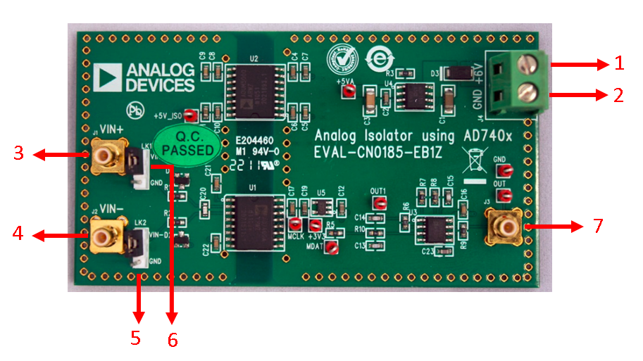
CN0185 is a complete low cost implementation of an analog-to-analog isolator. The circuit provides isolation of 2500 V rms (1 minute per UL 1577).
The circuit is based on the AD7400A , a second-order, sigma-delta (Σ-Δ) modulator with a digitally isolated 1-bit data stream output. The isolated analog signal is recovered with a fourth-order active filter based on the dual, low noise, rail-to-rail AD8646 op amp. With the ADuM5000 as the power supply for the isolated side, the two sides are completely isolated and use only one power supply for the system. The circuit has 0.05% linearity and benefits from the noise shaping provided by the modulator of the AD7400A and the analog filter. The applications of the circuit include motor control and shunt current monitoring, and the circuit is also a good alternative to isolation systems based on optoisolators.

1 - Connect the +6V power supply to this screw terminal (J4)
2 - Connect the GND terminal of the +6V power supply to this screw terminal (J4)
3 - Connect the positive analog input signal to this SMB connector (J1)
4 - Connect the negative analog input signal to this SMB connector (J2)
5 - LK2 jumper Pins 1 and 2 provides the connection of the positive analog input signal to the AD7400 and pins 2 and 3 puts the input to ground
6 - LK1 jumper Pins 1 and 2 provides the connection of the negative analog input signal to the AD7400 and pins 2 and 3 puts the input to ground
7 - Connect the Digital multimeter if measuring dc input and Spectrum analyzer/oscilloscope if measuring frequency response to this SMB connector (J3)
EVAL-CN0185-EBZ Design & Integration Files
Receive software update notifications, documentation updates, view the latest videos, and more when you register your hardware. Register to receive all these great benefits and more!
End of document