ADRV2CRR-FMC Production Testing
Overview
Production tests for ADRV9009-ZU11EG are composed of a series of Bash scripts that run both on Raspberry Pi and DUT (Device Under Test).
The test procedure requires a Raspberry Pi 4 board (host) connected via Ethernet cable to the DUT. The Raspberry Pi board requires to have a HDMI monitor and USB keyboard connected. All test sequences are selected and started from the GUI interface displayed by Raspberry Pi on the monitor. Please find the required equipment list below:
Required Hardware
Raspberry Pi4: Is strictly required to be version 4 or newer.
USB 3.0 connection is required during testing.
HDMI monitor: monitor should be connected to Raspberry Pi to display the testing sequence and the testing results
USB keyboard: keyboard should be connected to Raspberry Pi
USB 2.0 port (black). It is required to interact with the testing SW.
USB A-
USB type C cable: It is required to be connected between Raspberry Pi
USB 3.0 port (blue) and
USB-C connector of DUT when
USB device mode of DUT is tested. Will be displayed on test monitor
USB A – Micro
USB cable: Should be connected between Raspberry Pi
USB 2.0 port and DUT microUSB
UART connector (P8). This is required for
UART over
USB interface testing
Raspberry Pi microSD card: A minimum 8GB Class 10 microSD card prepared for testing sequence as presented bellow should be inserted in Raspberry Pi.
DUT
SD card: A minimum 8GB Class 10
SD card prepared for testing sequence as presented bellow should be inserted in ADRV2CRR-FMC P15 slot.
CAT5 ethernet cable: Using ethernet cable communication between Raspberry Pi and DUT is performed. On DUT side the ethernet cable should be connected on M2 port (Ethernet RGMII)
I2C programming cable: This cable is required to be connected between Raspberry Pi
I2C port (pins 3 - SDA, 2 - SCL and 6 – GND) and ADRV2CRR-FMC P19 pin header. Using this connection and item 1 from Raspberry Pi menu the ADM1266 sequencer can be programmed
USB-C power supply is required for powering up the Raspberry Pi
ADRV2CRR-FMC: is the carrier board that can be tested selecting item 3 on the test menu. It can be considered device under test or should be used as requirement when SOM is tested as support carrier for ADRV9009-ZU11EG RF-SOM
ADRV9009-ZU11EG RF-SOM: can be tested selecting item 4 from test menu. It can be tested or used when testing ADRV2CRR-FMC
QSFP loopback: should be connected to P3 on ADRV2CRR-FMC
SFP loopback: should be connected to P4 on ADRV2CRR-FMC
FMC loopback: should be connected to P1 on ADRV2CRR-FMC (Apissys AF101)
PCI-Express loopback: should be powered on using an
USB A – microUSB cable and connected to P17 on ADRV2CRR-FMC (Whizz Systems - PCIe Loopback Card)
Ethernet loopback: should be connected on M1 port (Ethernet SGMII) on ADRV2CRR-FMC
Audio loopback: should be connected to P6 and P5 connectors on ADRV2CRR-FMC
U.FL loopback cables: required for RF testing of ADRV9009-ZU11EG RF-SOM
Display Port to HDMI cable: should be connected to P2 video output on ADRV2CRR-FMC
USB-C OTG cable: should be connected when
USB host mode is tested
USB 3.0 memory stick: should be FAT formatted and connected through
USB-C OTG cable to ADRV2CRR-FMC when
USB host mode is tested
12V power supply: connected to P11 on ADRV2CRR-FMC.
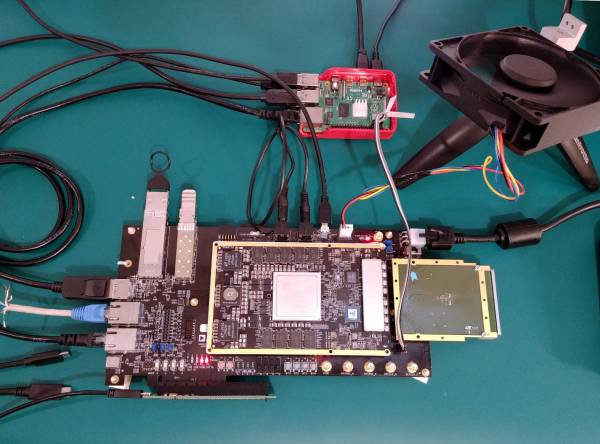
The complete test jig should look like:

Required Software
ADRV9009-ZU11EG SD card
The SD card image used for production testing is based on official release of Zynq images and can be downloaded from :
Raspberry PI SD card
The SD image used is based on Raspbian with desktop. On top of that are installed the testing scripts. The image can be created starting from vanilla Raspbian or downloaded from:
Required setup steps
Place the jumpers and switches in the following positions:
P22 in 2 and 3
P23, P24 in 1 and 2
S14, S15, S16 in 1
S13 in 0

P20, P18 in 1 and 2

S9 in “Carrier”

Connect HDMI cable to Raspberry Pi
Connect
USB keyboard to Raspberry Pi
Insert Raspberry Pi microSD card
Connect power supply to Raspberry Pi
Connect all loopbacks to DUT
Connect Ethernet cable between Raspberry Pi and DUT
Connect
USB cables between Raspberry Pi and DUT
-
Connect DisplayPort cable to DUT
Power on DUT
Test process
First make sure all the required setup explained above is completed. Once the test setup is ready, SOM testing should be done using the following steps:

When testing the ADRV2CRR-FMC the following test needs to be run: Test 3

Make sure that Ethernet cable is connected, DUT is powered up, DUT
SD card is inserted and boot mode switches (S13-S16) are configured for
SD boot.

Follow on-screen instructions to complete the test.
If test completed successfully the PASSED message will be printed in green like in the screen bellow. This means that DUT passed all the assigned tests.


In case of a failed test the program will ask if the tester wants to repeat that test immediately. The test can be repeated by an undefined number of times.
If the problem is persistent and the test failing continuously the test engineer can decide to not repeat it anymore.
In this situation it will be asked if user wants to close the test sequence and declare the DUT tested failed or can respond NO(n) to question “Do you want to close the test?” and in this way mark the test as passed and bypass it.
This is not recommended!
When testing is finished ADRV and Raspberry PI should always be powered off before power is unplugged otherwise the
SD cards can be corrupted. First should be selected item 9 to power off ADRV. The test engineer should wait until LEDs DS6 and DS7 are off. Now the power can be disconnected from ADRV. After ADRV is off the Raspberry PI can be turned off by selecting item 8.
