


The most recent version of this page is a draft. This version is outdated by a newer approved version.This version (23 Feb 2021 02:47) is a draft.
Approvals: 0/1
This version is outdated by a newer approved version.This version (23 Feb 2021 02:47) is a draft.Approvals: 0/1
This is an old revision of the document!
Table of Contents
ADMX1002, Ultra-low Distortion and Low Noise Signal Generator
Features
- SPI and ATE Communication
- On-board supply
- External common mode voltage option
- Sync In & Sync Out for Coherent Sampling
- External output clamp voltage option
- Differential to Single Ended Conversion
Package Contents
- ADMX1002 Module
- EVAL-ADMX1001-FMCZ Evaluation Board
- 12V wall adapter Power Supply
Additional Equipment Needed
SMA cables
Software Needed
ADMX1002 sourcing GUI
General Description
The ADMX1002 module is an ultra-low distortion and low noise signal generator. It offers a frequency range up to 40 kHz. ADMX1002 can be used with digital pre distortion (DPD) algorithm of up to 20 kHz and has distortion performance up to 130dB typical at 1 kHz. A flexible digital interface allows for easy integration into any system. The ADMX1002 evaluation kit demonstrates the best in class signal source performance of the ADMX1002 module. The module can be shown to achieve better that -125dB THD, with SNR figures typically greater that 117dB. The evaluation board kit includes an intuitive GUI for sourcing. This interface communicates to the module via a USB to SPI through the SDP-B or SDP-S.

Figure 1. ADMX1002 Evaluation Board
ADMX1002 Evaluation Board
Figure 2 shows the ADMX1002 evaluation board. Following are the connectors, inputs and output related to the evaluation board:
- ADMX1002 Module connector: Two recommended connector part are HSEC8-140-01-S-DV-A-WT for vertical and HSEC8-140-01-S-RA for horizontal mount connector both from SAMTEC.
- Source PMOD connector
- Power Supply: The ADMX1002 evaluation board is powered from a 12V wall adaptor via P14. The evaluation board provides on-board supply regulators to generate the +3.3, and ±9V required to power the module.
- SMA connector
Table 1. SMA Connector
| Connector | Description |
|---|---|
| OUTP | Source positive output |
| OUTN | Source negative output |
| SINGLE ENDED OUTPUT | Source single ended output |
| INN | Reserved |
| INP | Reserved |
| ACQ_SYNC_IN | Reserved |
| SYNC_IN | Reserved |
- Jumper and Switch Setup
Table 2. Jumper and Switch Setup
| Name | Function | Position |
|---|---|---|
| P4 | VCM from DAC or EXT | 1-2 (VCM_DAC) |
| P6 | EN | Removed |
| P8 | Sense Input Clamp to +5V | Inserted |
| P9 | Sense Input Clamp to -5V | Inserted |
| P11 | Reserved | Removed |
| P12 | Reserved | Removed |
| P13 | Reserved | Removed |
| S1 | Reserved | loopback off |

Figure 2. ADMX1002 Evaluation Board
QUICK START GUIDE
Equipment
Figure 3 illustrates the required setup for evaluation of the ADMX1002 module. The following equipment are required to perform a full evaluation:
- ADMX1002 kit that contains:
- ADMX1002 module
- ADMX1002 evaluation board
- Power adaptor
- 6-pin PMOD cable
- SDP-S or SDP-B
- PMOD interposer board
- Windows PC, Windows 7 or Windows 10
- SMA cables for connection from evaluation board to analyzer
SETUP
- Check Jumper & Switch settings (check Jumper/Switch Set up section)
- Connect evaluation board to power supplies
- Apply the evaluation board power & check the voltage rails (+9V, -9V and +3.3V)
- Remove power & insert ADMX1002 module
- Connect the SDP interposer board to the “SOURCE/DAC SPI” header on the eval board through the 6 pin PMOD cable.
- Caution: Check table 3 for jumper connection
- Caution: Check Figure 3 to connect the SPI cable in the right position.
- Connect USB Cable from PC to SDP-S or SDP-B
- Apply the PMOD interposer board power and wait for 10 seconds
- Apply the evaluation board power
- Start ADI ADMX1002 GUI and press Connect (check software installation section).
SETUP
The SDP_S or SDP_B will be connected to the ADMX1002 through SPI via PMOD interposer board.
Table 3. PMOD Interposer Board Jumpers and Connectors
| Name | Function | Position |
|---|---|---|
| JP1 | SPI/UART selector | SPI |
| JP2 | VPIO | Removed |
| P4 | SPI/UART connector | SPI (Pin1-6) |

Figure 3. SDP-PMOD Interposer Board Jumper Connection
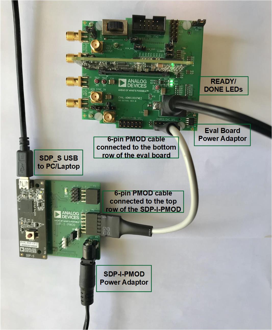
Figure 4. Evaluation Board Connection
SOFTWARE OPERATION
ADMX1002 SOURCING GUI TOOLBAR AND STATUSBAR OVERVIEW
- (A) Connect/Disconnect – Click to connect eval board to PC
- (B) Run – This button runs the signal.
- (C) Stop – This button stops any running signal.
- (D) Calibrate – This button runs the digital pre distortion (DPD) algorithm.
- (E) Trigger Mode – Use this to change selection to either “Continuous” or “Single-shot”.
- (F) Signal Type – Use this to change selection to either “Alternating”, “Direct”, “IMD” or “AWG File”.
- (G) Write – This button writes the “set” values and reads the “generated” parameters to the ADMX1002 module. The generated parameters will then be displayed at the Generated Parameters Panel.
- (H) Set Parameters Configuration – Amplitude and Frequency levels can be changed here.
- (I) Profile Save
- (J) Profile Load
- (K) Use Profile checkbox – Check when loading profiles; otherwise, uncheck.
- (L) Set the maximum number of profiles.
- (M) Profile Id – Change id accordingly.
- (N) Signal Plot – Shows the signal preview.
- (O) Generated Parameters Panel – Displays parameters read from the module.
- (P) Status Message – The status of the software will be displayed here.
- (Q) Timer – Shows the timer on some status. During running, DPD algorithm, and writing of AWG data, a timer will be shown.
- (R) POST/BIST
- (S) Opens the Log Window
- (T) Opens the Registers Read/Write Window
- (U) Versioning – Firmware Version, Verilog Version and PCB Version
- (V) Module ID
- (W) SPI Data Rate
- (X) Controller Board Type – Defaulted to SDP
- (Y) Help
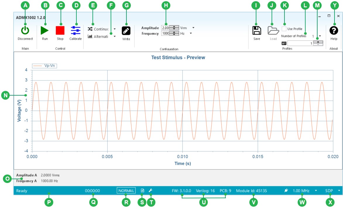
Figure 5. ADMX1002 Sourcing GUI overview
RUN WITHOUT DIGITAL PRE-DISTORTION (DPD)
The following sequence shall produce a signal without (DPD) algorithm (see Figure 5 for the label):
- Set desired parameters (H).
- WRITE parameters (G). Panel in (O) will display the generated configuration of the signal.
- RUN parameters (B). The Status Bar (P) should display “Ready” and the timer beside it should start. This means that the ADMX1002 module is now processing the configuration. It should change to “Busy” after a short while and display the time elapsed, indicating ADMX1002 is now sourcing the configuration. This generates a signal without DPD.
- STOP (C) will immediately terminate the signal generation. The Status Bar in (P) will then display “Stop / Ready.”
RUN WIT DIGITAL PRE-DISTORTION (DPD)
The following sequence shall produce a signal with DPD algorithm:
- Set desired parameters (amplitude and frequency) (H).
- WRITE parameters (G). Panel in (O) will display the generated configuration of the signal.
- Click Calibrate (D). A “Calibrating…” status will be seen in the Status Bar (P) and the timer (Q) will start. Wait until the Status Bar (P) will change to “Calibrated” and display the time elapsed. This process may take up to 2 minutes.
- RUN (B). The Status Bar (P) should display “Ready” and the timer beside it should start. It should change to “Busy” after a short while and display the time elapsed, indicating ADMX1001 is now sourcing the configuration. This generates a signal with DPD.
- STOP (C) will immediately terminate the signal generation. The Status Bar (P) will then display “Stop / Ready.”

Figure 6. Setting Parameters for Generating a Single-tone Signal With and Without DPD (Continuous mode)
GENERATE TWO-TONE SIGNAL
The following sequence shall produce a two-tone signal assuming the GUI is already connected (see Figure 6 for the label):
- Change the Signal Type (F) to “IMD”. The CALIBRATE button is disabled since it is only allowed in sinewave.
- Set desired parameters (H). A signal preview will be plotted (N).
- WRITE parameters (G). Panel in (O) will display the generated configuration of the signal.
- RUN parameters (B). The Status Bar (P) should display “Ready” and the timer beside it should start. This means that the ADMX1002 module is now processing the configuration. It should change to “Busy” after a short while and display the time elapsed (Q), indicating ADMX1001 is now sourcing the configuration.
- STOP (C) will immediately terminate the signal generation. The Status Bar in (P) will then display “Stop / Ready”.
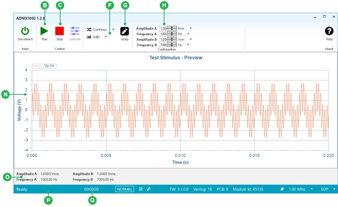
Figure 6. Setting Parameters for a Two-tone Signal
GENERATE DC SIGNAL
The following sequence shall produce a DC signal assuming the GUI is already connected (see Figure 7 for the label):
- Change the Signal Type (F) to “Direct”. The CALIBRATE button is disabled since it is only allowed in sinewave. The only allowed Trigger Mode is “Continuous”.
- Set desired parameters (H). A signal preview will be plotted (N).
- WRITE parameters (G). Panel in (O) will display the generated configuration of the signal.
- RUN parameters (B). The Status Bar (P) should display “Ready” and the timer beside it should start. This means that the ADMX1002 module is now processing the configuration. It should change to “Busy” after a short while and display the time elapsed (Q), indicating ADMX1001 is now sourcing the configuration.
- STOP (C) will immediately terminate the signal generation. The Status Bar in (P) will then display “Stop / Ready”

Figure 7. Setting Parameters for a DC Signal
GENERATE SINEWAVE SIGNAL (SINGLE-SHOT)
All the previous software operation examples have the trigger mode set to “Continuous”. Now let us try the other option which is “Single-shot”. The signal duration of this mode is based on the number of samples defined. The following sequence shall produce a sinewave signal with trigger mode set to single shot, assuming the GUI is already connected (see Figure 8 for the label):
- Change the Signal Type (F) to “Alternating”.
- Change the Trigger Mode (E) to “Single-shot”.
- Set desired parameters (H). The default number of cycles is 100. A signal preview will be plotted (N).WRITE parameters (G). Panel in (O) will display the generated configuration of the signal.
- RUN parameters (B). The Status Bar (P) should display “Ready” and the timer beside it should start. This means that the ADMX1001 module is now processing the configuration. It should change to “Busy” after a short while and display the time elapsed (Q), indicating ADMX1001 is now sourcing the configuration.
- STOP (C) will immediately terminate the signal generation. The Status Bar in (P) will then display “Stop / Ready”.
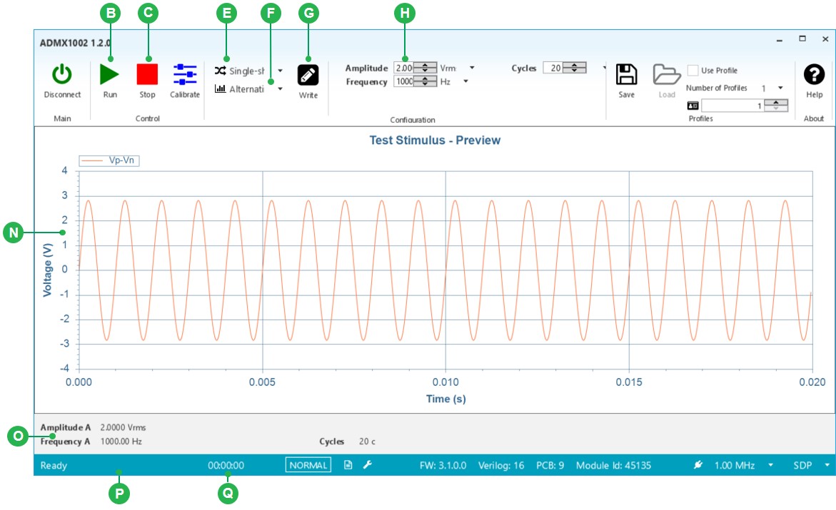
Figure 8. Setting Parameters for a Sinewave Signal (Single-shot Mode)
STORING PROFILES
The following sequence shall save a profile (see Figure 9 for the label):
- (Optional) Change the “Number of Profiles” (L) stored from default. A dialog box “CHANGE NUM PROFILES” will appear stating that, “The module must be rebooted if the number of profiles is changed.” A power cycle must be done on the board to reboot it for this to take effect.
- Make sure to UNCHECK the “Use Profile” checkbox (K).
- For each profile to save:
- STOP (C) any running signal.
- Select the Profile ID (M) to associate with the profile to store.
- Set (H) desired parameters (Amplitude and Frequency). The plot will automatically display the waveform that corresponds to the parameters entered.
- Write parameters (G). Panel (O) will display the Amplitude and Frequency settings of the signal.
- (Optional) Calibrate (D). The Status Bar in (P) will change from “Ready” to “Calibrating…” status and the timer (L) beside it will start. After calibrating the signal, (P) will say it is “Calibrated” and display the time elapsed (L).
- RUN (B) and STOP (C).
- Click the SAVE profile button (I). Status Bar (P) will display “Saving Profile…” first and then “Profile Saved” indicating it has already saved the settings with the associated Profile ID.
- Repeat (3) for additional profiles to save.
- Note: Make sure to select a different Profile ID number for each profile, otherwise, the previous will get overwritten.

Figure 9. Saving Profile at profile id 1
LOADING PROFILES
The following sequence shall load previously saved profile (see Figure 10 for the label):
- STOP (C) any running signal. The Status Bar (P) will display “Stop / Ready”.
- CHECK the “Use Profile” checkbox (K)
- Select the saved Profile ID. (M)
- Click the LOAD profile button (J). The Status Bar (P) will be displaying “Loading Profile…” first, then “Profile Loaded (Not Calibrated)” (for signals without DOD) or “Profile Loaded (Calibrated)” (for signals with DPD).
- Loaded profile parameters (amplitude and frequency) from the selected Profile ID will be visible in (O).
- Run (B) the loaded profile. Status Bar (P) should display “Ready” and the timer (L) beside it should start. This means that the ADMX1001 module is now processing the configuration. It should change to “Busy” after a short while and display the time elapsed (L), indicating ADMX1001 is now sourcing the configuration.
USING A DIFFERENT SAVED PROFILE
- STOP (C) any running signal. The Status Bar (P) will display “Stop / Ready”.
- With the “Use Profile” checkbox (K) still checked, select another Profile ID (M) with previously stored profile.
- Click the LOAD profile button (J). The Status Bar (P) will display “Loading Profile” first, then “Profile Loaded (Not Calibrated)” (for signals without DPD) or “Profile Loaded (Calibrated)” (for signals with DPD).
- Loaded profile parameters (amplitude and frequency) from the selected Profile ID will be visible in (O)
- Run (B) the loaded profile. Status Bar (P) should display “Ready” and the timer (L) beside it should start. This means that the ADMX1001 module is now processing the configuration. It should change to “Busy” after a short while and display the time elapsed (L), indicating ADMX1001 is now sourcing the configuration.

Figure 10. Loading Profile with profile id 1
resources/eval/user-guides/admx/admx100x.1614044834.txt.gz · Last modified: 23 Feb 2021 02:47 by Gustavo Castro