


This version (11 Feb 2021 12:21) was approved by Catherine Redmond, Aaron Paulo Heredia.The Previously approved version (11 Feb 2021 12:17) is available.
Table of Contents
ADIN1300 and ADIN1200 with Capacitive Coupling
ARCHITECTING A TRANSFORMERLESS PHYSICAL LAYER DEVICE USING ADIN1300/ADIN1200
Introduction
Ethernet applications typically use galvanic isolation in the form of magnetics between link partners. The isolation helps to protect against faults and transients in addition to achieving the best electromagnetic compatibility performance. Magnetic coupling between the PHY and the RJ45 is the most common way of achieving this isolation as shown in Figure 1 (a). Some applications choose to forgo magnetics for various reasons, typically space or cost, or both. Moving into a transformer-less operation, isolation in accordance with the IEEE 802.3 standard is obtained by choosing capacitive coupling instead of magnetic coupling. This application note captures detail around using the ADIN1300 and ADIN1200 Ethernet PHY with capacitive coupling and covers discussion on the typical circuit, recommended capacitor.
ADIN1300 and ADIN1200 Ethernet PHY
The ADIN1300 and ADIN1200 are low power, low latency single-port Ethernet transceivers designed for industrial Ethernet applications. Both are compliant with the IEEE 802.3 Ethernet standard. The ADIN1300 supports 10/100/1000 Mbps and ADIN1200 supports 10/100 Mbps Ethernet speeds. These PHYs support unmanaged configuration using multi-level strapping, or managed configuration using MDIO access and operate over a wide industrial temperature range (−40°C to + 105°C). The ADIN1300 and ADIN1200 support MII, RMII, and RGMII MAC interfaces. More information about ADIN300 and ADIN1200 is found in the product datasheets.
Application Circuits
Figure 1(a) shows a typical ADIN1300 (or ADIN1200) Ethernet PHY Media Dependent Interface Connection with magnetics for galvanic isolation. Figure 1(b) shows the recommended circuit using capacitive coupling. In this case, the transformer is replaced with a capacitor in each path from MDI pins to the RJ-45 connector. Proper selection of capacitors, layout recommendations, and other guidelines are discussed in the succeeding sections.

Figure 1. Typical Ethernet application configuration for ADIN1300 with Magnetics (a) or Capacitive Coupling (b)
For ADIN1200, two pairs of the MDI must all contain a capacitor, the same as the ADIN1300. Figure 2 shows the recommended circuit for capacitively coupled ADIN1200 circuit.
![]() Figure 2. Typical Ethernet application configuration for ADIN1200 with Magnetics (a) or Capacitive Coupling (b)
Figure 2. Typical Ethernet application configuration for ADIN1200 with Magnetics (a) or Capacitive Coupling (b)
Capacitor Selection
Select the capacitors based on the following guidelines.
- Using non-polarized capacitors.
- The capacitors must meet the isolation requirements as specified in Clause 40.6.1.1(ac and dc isolation).
- Use 33 nF capacitor value as recommended.
Choosing the Capacitor
The capacitor value is calculated by following the required 3 radians phase angle over a frequency range of 2-80 MHz according to ANSI INCITS 263-1995 in order to meet the return loss requirement according to IEEE 802.3 33.4.7 subclause.


The value of recommended capacitance would be C = 30.369 nF ≈ 33 nF
Where:
- f = 2 MHz as the frequency of interest for worst-case condition
- Zo = 100 ohms
Use an NPO capacitor as it exhibits tighter tolerance (0.1%) than any other cap type. Any difference from the capacitances might greatly affect the differential signal and there could be a deviation in signal rise/fall time, propagation delay, magnitude deviation that results in common-mode noise.
ADIN1300 & ADIN1200 MDI Properties
The ADIN1300 and ADIN1200 PHY are voltage-driven PHYs on the MDI with 50 ohms (each pin) serial resistors. The proper common mode is half the supply voltage (3.3V/2) and the Tx drivers provide this DC voltage automatically. Since the common mode is controlled by the Line Driver, the MDI pins should not use any pull-up or pull-down resistors for proper biasing, either with or without a transformer.
Protection
Place a TVS on the MDI lines of the ADIN1300 and ADIN1200 for protection against ESD, fast transients, and surges. The TVS is placed in between the ADIN1300/ADIN1200 MDI pins and blocking capacitors.
 Figure 3. TVS and Common Mode Choke Applied to ADIN1300/ADIN1200
Common Mode Noise
When the capacitive coupling is used for configurations with cabling, common-mode noise could be induced, thus a filter is necessary to remove those CM noises. Using a common mode choke gives better common-mode rejection. For short connections, such as backplane applications, there should be little common-mode noise induced, so a choke is likely not required.
Configurations
The most common application where capacitively coupled Ethernet PHYs are used is in backplane applications where a single cap can be used to isolate the two nodes that are attached to the backplane using ethernet compliant connectors. Capacitive coupling may also be used in applications requiring a short cable less than 1 meter.
Single Cap Configuration
This configuration can be used for backplane applications where the two nodes are attached to the backplane. This configuration uses PCB traces as the connecting medium for the two nodes. The PCB traces must be 50 ohms. A single blocking capacitor separates the two nodes in the backplane. This configuration doesn’t necessarily include a common mode choke. The PCB traces must be of equal lengths to have a well-balanced impedance because any unbalanced path would introduce common-mode noise.
A benefit of using capacitive coupling is a smaller footprint than magnetics, which is very useful in backplane applications. Figure 4 shows a single cap configuration using ADIN1300.
Cap - Cable - Cap Configuration
The cap-cable-cap approach is similar to the backplane application but the two nodes use short Ethernet compliant wires instead of copper PCB traces as connecting medium. Figure 5 shows a simple illustration of the cap-cable-cap using the ADIN1300/ ADIN1200. This configuration would work well when the cable is 1 meter or less. Anything more than 1 meter might introduce some common-mode noise. Commonly, these two boards belong to one shielded casing. A common mode choke might not be needed in this configuration as common mode noise induced is very low. There are situations (non-backplane), mostly in industrial applications, where the nodes are separated at longer distances, using a long cable (more than 1 meter), therefore, it is recommended to use a common mode choke to attenuate the noise. The cable can also be shielded as an additional immunity.
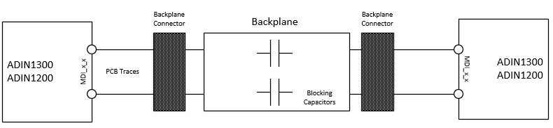
Figure 4. ADIN1300 Configuration for Backplane Applications (Single Capacitor)

Figure 5. Capacitive Coupling Configuration (with Cable)
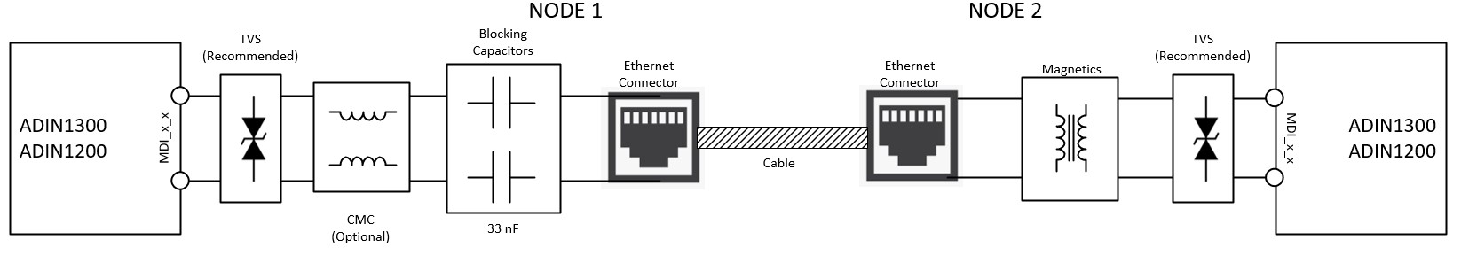
Figure 6. Capacitive and Magnetic Coupling Configuration (with Cable)
Cap - Cable - Transformer Configuration
The Cap-Cable-Transformer approach is a non-typical ethernet connection, shown in Figure 6. It is important to note that Node 1 uses capacitive coupling and Node 2 uses Magnetic coupling and the two nodes are connected via ethernet cable. The Ethernet cable must not exceed one meter because one of the nodes uses capacitive coupling. It is best to use a shielded Ethernet cable when using this type of configuration. However, if the two nodes are separated at longer distances, using longer ethernet cables, then it is highly recommended to add a common mode choke.
Evaluation
The ADIN1200 and ADIN1300 are capable of operating at all speeds with the capacitively coupled configuration in both forced and auto-negotiation modes. The driver architecture supports symmetrical transmission in all modes. Figure 7 to Figure 10 show typical signaling for transformer and capacitively coupled configurations measured at the cable. Evaluation under nominal supply and temperature conditions using the ADIN1300 capacitively coupled (local and remote) showed no packet loss, no CRCs errors and signal quality (MSE – mean square error) remained comparable to transformer arrangement over a range of cable lengths (2 m to 100 m). In industrial applications, where common mode noise may be significant as already discussed, a common mode choke is recommended where there are long cable lengths.
| Transformer | Capacitive Coupling |
|---|---|
 |  |
| Figure 7. 100 Mbps with Transformer circuit | Figure 8. 100 Mbps with Capacitive Coupling |
 |  |
| Figure 9. 10 Mbps with Transformer circuit | Figure 10. 10 Mbps with Capacitive Coupling |
EMC Simulation
Computing power, SPICE, electromagnetic field simulators, and CAD software have converged and reached a maturity point where a virtual lab is feasible. Simulating an Ethernet link with ADIN1300 PHY, PCB, cable models, EMC source (stimulus), and active/passive components is possible.
When considering EMC performance for an Ethernet link both transient immunity and radiated emissions require careful consideration.
EMC - transient immunity
- High voltage transients, such as IEC 61000-4-4 EFT to the Cat5e cable will result in overvoltage at the Ethernet ADIN1300 MDI pins.
- If using capacitive isolation, a TVS is recommended to clamp the overvoltage.
- Using a low capacitance TVS, such as the SP4065-08ATG will help to protect the ADIN1300 Ethernet PHY.
- There are many ‘high speed’ TVS options available, however the clamp voltage vs. current specification varies.
- The Littlefuse SP4065-08ATG has a lower clamp voltage at high current compared to other devices.
- Littlefuse provide SPICE parameters for the SP4065-08ATG .
EMC - radiated emissions
- An ethernet transformer, with integrated common mode choke (CMC) provides very good common mode noise attenuation.
- Without a transformer and integrated CMC, any common mode noise from the Ethernet PHY driver will go straight to the cable and radiate very efficiently. More radiation will occur with a longer cable.
- If using a longer cable (> 2m) it is recommended that the customer add a discrete CMC to the interface.
Figure 11 shows a block diagram representation of an EMC simulation schematic. This simulation investigates the robustness of the Ethernet physical interface to IEC 61000-4-4 Electrical Fast Transients (EFT). The EFT source is injected at 1kV and at 4kV. The TVS used is the SP4065-08ATG, with 4.4pF typical capacitance, and a 1A clamp voltage of 5.5V. Two meters of standard Cat5e is used in the simulation model. The EFT source is injected through a 100 pF capacitor to the Cat5e cable shield, at 0.5 meters from the Ethernet interface. The interface includes 33nF series capacitive isolation.
 Figure 11. EMC simulation block diagram
Running this simulation without TVS results in overvoltage on the Ethernet MDI pins. Figures 12 (for 1 kV EFT) and 13 (for 4 kV EFT) show that 100 to 400V overvoltage will be present on the Ethernet MDI pins.
 Figure 12. Running simulation without TVS and 1 kV EFT
 Figure 13. Running simulation without TVS and 4 kV EFT
Running this simulation with TVS results in much better performance. Most of the EFT noise is shunted to ground using the TVS, as shown in Figures 14 and 15. The pin voltage is < 10V for very short time periods, unlikely to cause ADIN1300 damage. The ringing in some of the waveform edges is very high frequency, & very unlikely to be present in the real system.
 Figure 14. Running simulation with TVS and 1 kV EFT
 Figure 15. Running simulation with TVS and 4 kV EFT
When adding the TVS to the Ethernet capacitive isolation architecture there is one additional question - is there any degradation in signal integrity? This can be simulated by injecting a MLT-3 31.25 MHz signal on each MDI pin (corresponding to 100 Mbps Ethernet MII). Simulation shows that adding 33nF series capacitors, with TVS and 2 meters of cabling does not attenuate signaling. Some minor signal reflections are likely to occur (due to cable effects) as shown in Figure 16, but differential signaling levels are not effected.
 Figure 16. Signal integrity simulation - using Capacitive Isolation and TVS on the MDI Interface
Conclusion
When architecting a physical layer circuit using capacitively coupled ADIN1300 and ADIN1200, consider the cable length to be used. Any cable more than 1 meter would introduce noise that can be eliminated by putting a common mode choke in the MDI signal path and shielding the ethernet cable. Use NPO 33 nF capacitors in designing the circuit. Include a TVS for immunity to ESD and fast transients. For backplane applications, the PCB traces must be of the same length with 50 ohms impedance.
resources/eval/user-guides/adin1300-and-adin1200/cap-coupling.txt · Last modified: 11 Feb 2021 12:21 by Catherine Redmond