


This version is outdated by a newer approved version. This version (08 Oct 2014 12:57) was approved by Aidan Frost.The Previously approved version (08 Oct 2014 12:28) is available.
This version (08 Oct 2014 12:57) was approved by Aidan Frost.The Previously approved version (08 Oct 2014 12:28) is available.This is an old revision of the document!
Table of Contents
MathWorks Simulink Model of AD7403
A model of the AD7403 is provided here for functional demonstration. It can accept various sources (for example: ramp, constant, sinusoid etc) and there is the option to apply a sinc filter to the output. The sinc filter is necessary to reconstruct the original information, by digitally filtering and decimating the modulator output.
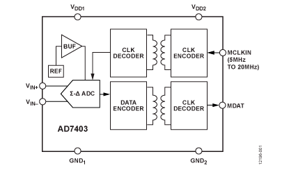
The AD7403 is a high performance, second-order, Σ-Δ modulator that converts an analog input signal into a high speed, single-bit data stream, with on-chip digital isolation based on Analog Devices, Inc., iCoupler® technology. The AD7403 operates from a 5 V (VDD1) power supply and accepts a differential input signal of ±250 mV (±320 mV full-scale). The differential input is ideally suited to shunt voltage monitoring in high voltage applications where galvanic isolation is required.
The analog input is continuously sampled by a high performanceanalog modulator, and converted to a ones density digital output stream with a data rate of up to 20 MHz. The original information can be reconstructed with an appropriate digital filter to achieve 88 dB signal to noise ratio (SNR) at 78.1 kSPS.The serial input/output can use a 5 V or a 3 V supply (VDD2).The serial interface is digitally isolated. High speed complementarymetal oxide semiconductor (CMOS) technology, combined with monolithic transformer technology, means the on-chip isolation provides outstanding performance characteristics, superior to alternatives such as optocoupler devices. The AD7403 device is offered in a 16-lead, wide-body SOIC package and has an operating temperature range of −40°C to +125°C.
In order to run the AD7403 model, your MATLAB license needs to include the following components:
- MATLAB (R2014a and beyond)
- Simulink
Downloads
- This link provides a download of the .zip file. Simply extract the .zip and launch AD7403.slx. This will launch MATLAB and Simulink.
User Notes
To use the AD7403 model, ensure all the above packages are installed and download the zip file here. Extract the files, and double click on
AD7403.slx
.
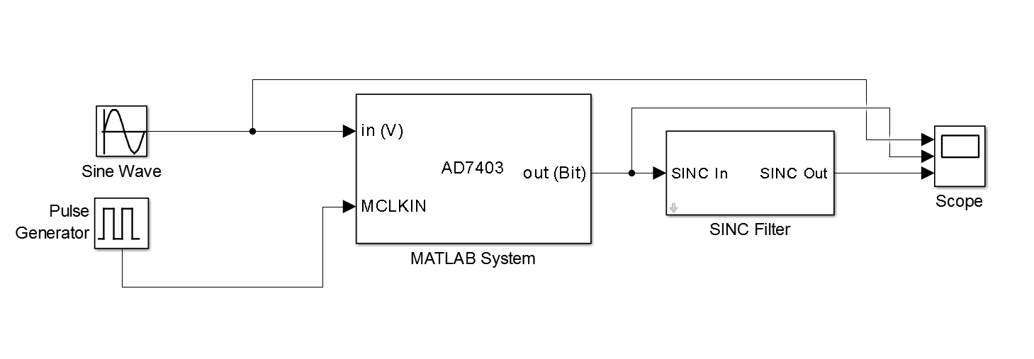
On opening Simulink, the following block diagram will appear.
If it is the first time running MATLAB, then it will need to be configured to use a compiler. To do this type the command
mex -setup
This brings up the following window where a compiler can be selected.

Various sources can be used as inputs to the model. Here, a Sine Wave source is used. A ramp or constant input can also be employed.
The parameters of the sinc filter can be edited by double clicking on the relevant block. This launches the following window.
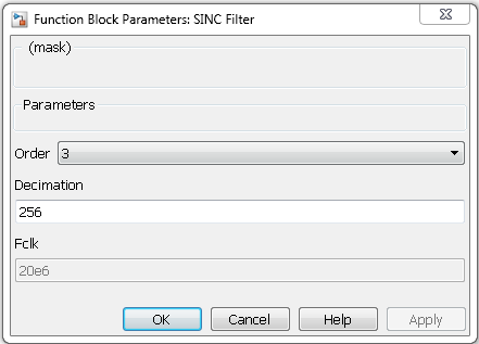
The order of the filter and the decimation rate can be adjusted here.
Running the model using the default conditions will result in the following output from the modulator and sinc filter.

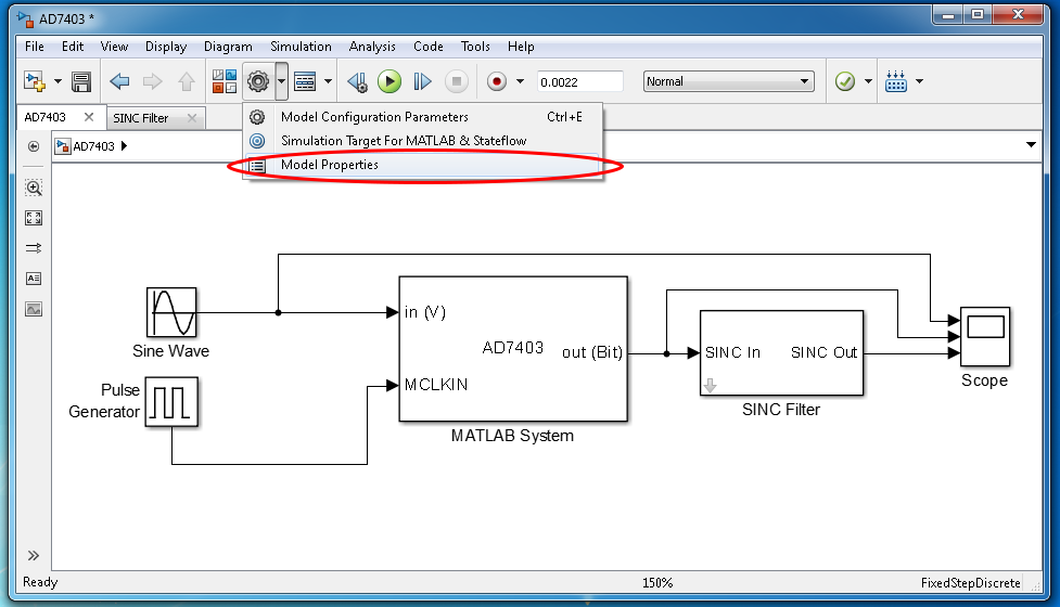
It is possible to change the FCLKIN frequency of the model. It is a global variable within the model as both the AD7403 and the SINC filter utilise it. To edit the variable, select Model Properties → Callbacks → InitFcn* See below images.

resources/eval/user-guides/ad7403.1412765745.txt.gz · Last modified: 08 Oct 2014 12:55 by Aidan Frost