 This version (23 Jul 2012 13:18) is a draft.
This is an old revision of the document!
ezLINX™ iCoupler® Isolated Interface Development Environment Homepage
Two Isolated SPI ports are implemented using the ADuM3401 and the ADuM3402 iCoupler signal isolators and the ADuM5000 isoPower Isolated DC to DC converter. The ADuM3401 of the isolated SPI1 is connected to SPI0 of the ADSP-BF548. The ADuM3402 is used for isolating the SPI slave select lines. Figure 1 below shows a circuit diagram of the implementation of Isolated SPI1 using the ADuM3401, ADuM3402, and ADuM5000 on the ezLINX hardware.

To connect Isolated SPI1 as a master, connect jumpers JP5, JP7, JP9, JP11, JP13, JP15, JP21 and JP36 while leaving jumpers JP6, JP8, JP10, JP12, JP14, JP16, JP20 and JP37 open. To connect Isolated SPI1 as a slave, connect jumpers JP6, JP8, JP10, JP12, JP14 and JP16 while leaving jumpers JP5, JP7, JP9, JP11, JP13 and JP15 open. When connecting SPI1 as a slave JP20 should also be connected, enabling the slave select and serial clock inputs on the ADuM3402.
These jumper settings are given in the table below:
| JP5 | JP6 | JP7 | JP8 | JP9 | JP10 | JP11 | JP12 | JP13 | JP14 | JP15 | JP16 | JP20 | JP21 | JP36 | JP37 | |
|---|---|---|---|---|---|---|---|---|---|---|---|---|---|---|---|---|
| SPI1 Master | Connect | Open | Connect | Open | Connect | Open | Connect | Open | Connect | Open | Connect | Open | Open | Connect | Connect | Open |
| SPI1 Slave | Open | Connect | Open | Connect | Open | Connect | Open | Connect | Open | Connect | Open | Connect | Connect | Open | Open | Connect |
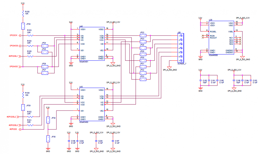
The ADuM3401 of the isolated SPI2 is connected to SPI2 of the ADSP-BF548. The ADuM3402 is used for isolating the SPI slave select lines. Figure 2 below shows a circuit diagram of the implementation of Isolated SPI2 using the ADuM3401, ADuM3402 and ADuM5000 on the ezLINX hardware.

To connect Isolated SPI2 as a master, connect jumpers JP22, JP24, JP26, JP28, JP30 and JP32 while leaving jumpers JP23, JP25, JP27, JP29, JP31 and JP33 open. To connect Isolated SPI2 as a slave, connect jumpers JP23, JP25, JP27, JP29, JP31 and JP33 while leaving jumpers JP22, JP24, JP26, JP28, JP30 and JP32 open. When connecting SPI2 as a slave JP34 should also be connected, enabling the slave select and serial clock inputs on the ADuM3402.
These jumper settings are given in the table below:
| JP22 | JP23 | JP24 | JP25 | JP26 | JP27 | JP28 | JP29 | JP30 | JP31 | JP32 | JP33 | JP34 | JP35 | JP38 | JP39 | |
|---|---|---|---|---|---|---|---|---|---|---|---|---|---|---|---|---|
| SPI2 Master | Connect | Open | Connect | Open | Connect | Open | Connect | Open | Connect | Open | Connect | Open | Open | Connect | Connect | Open |
| SPI2 Slave | Open | Connect | Open | Connect | Open | Connect | Open | Connect | Open | Connect | Open | Connect | Connect | Open | Open | Connect |
VDD1 of the ADuM3401, ADuM3402 and VDD1 of the ADuM5000 are powered by 3.3V. The ADuM5000 will generate an isolated 3.3V and is used to supply power to VDD2 of the ADuM3401 and ADuM3402.
Two seven pin screw terminal connectors, J10 and J25 are used for easy access to the SPISCK (Pin 1), SPIMOSI (Pin 2), SPISEL1/SPISS (Pin 3), SPIMISO (Pin 4). SPISEL2 (Pin 5), SPISEL3 (Pin 6) and SPI_ISO_GND (Pin 7).