Navigation
Preface
This user guide describes how to acquire data capture from AD9106-ARDZ-EBZ/AD9102-ARDZ-EBZ evaluation board to characterize AD9106/AD9102 high-speed digital-to-analog converter. It focuses on how the evaluation board works with SDP-K1 controller board and Analysis Control Evaluation (ACE) Software both developed by Analog Devices.
The evaluation setup can be powered by USB only and does not require a high-frequency waveform generator for clock input. The evaluation board has an on-board 156.25 MHz crystal oscillator. To fit the evaluation system in a small form factor and manage power consumption within USB specifications, AD9106 and AD9102 supply voltages AVDD, DVDD and CLKVDD are limited to 3.3V only.
Software Needed
Quick Start Guide
Attach AD9106-ARDZ-EBZ / AD9102-ARDZ-EBZ evaluation board to SDP-K1. Make sure SDP-K1 VIO is set to 3.3V through the P14 jumper by placing the shunt on the center and 3.3V pins, refer to Figure 1.
 Figure 1. SDP-K1 VIO Configuration
Note: If the VIO is set to 1.8V, 0xFFFF data will be read to all registers in the memory map and can't apply data changes to all registers.
Connect SDP-K1 to PC over
USB. DS1 and DS2 on SDP-K1 and DS1 on the evaluation board should light up. If DAC outputs are connected to the on-board amplifiers, connect a 7V to 12V 30W wall wart to SDP-K1 DC Jack or to P15 on the evaluation board.
Connect the outputs of the evaluation board to an oscilloscope using SMA to BNC cables. Apply the oscilloscope settings shown in the waveform captures of the example patterns in Figures 5a and 5b.
-
In ACE, select the settings enumerated below and shown in Figure 2a or 2b. Click Apply.
Click the AD9106 / AD9102 Chip to proceed to chip view. Apply the chip settings enumerated below and shown in Figure 3.
DDS Output Frequency: 10MHz
Waveform Selector Dropdown Menus: Prestored
Prestored Waveform Selector Dropdown Menus: DDSx output
DAC1 Dig Gain: 1
DAC2 Dig Gain: 0.75
DAC3 Dig Gain: 0.5
DAC4 Dig Gain:
0.25
 Figure 3a. AD9106 Chip View
 Figure 3b. AD9102 Chip View
Click
Apply Changes to update
SPI register values.
 Figure 4. AD910x Apply Changes Button in Chip View
Click Trigger to generate output waveforms. Waveform captures are shown in Figures 5a and 5b.
 |  |
| Figure 5a. EVAL-AD9106 10MHz DDS Sinewave with Digital Gain Settings | Figure 5b. EVAL-AD9102 10MHz DDS Sinewave |
There are six available sample waveform settings that can be loaded from the plugin to the device.
From chip view, click Load Sample Waveforms at lower left side of the window.
-
To modify sample waveform, either
click Back to AD910x then modify the settings from the chip view; or
open Memory Map then change register values.
Click Apply Changes then Trigger.
Extracting power up sequence and SPI registers
When transitioning from an evaluation platform to custom designed hardware it is often necessary to understand the state of the hardware settings or interactions occurring during an evaluation session. ACE provides the option to Export Interaction With Hardware.
Figure 7. AD9106 ACE Macro Tool
Expand Tools and select Macro Tools from the left side pane of ACE. This should open the Macro Tool at the right side pane.
Click Record button.
Apply settings as needed. After completing some interactions with the
GUI, press the stop icon.
The macro can be edited by choosing steps to skip or adding comments. It macro can be exported to be used as a reference for the interactions that happened in the session, or to replay in a different session
Using Memory Map
The user can also opt to use Memory Map to Extract SPI Register Settings at the time of waveform generation.
From Chip View, click Proceed to Memory Map.
Click Read All and Export.
Save the Export file.
Modifying SRAM Vectors
The AD910x ACE plugin includes an SRAM Control feature that can be used to Generate Waveform and Load waveform into SRAM. This is accessible from the chip view by clicking Proceed to SRAM Control.
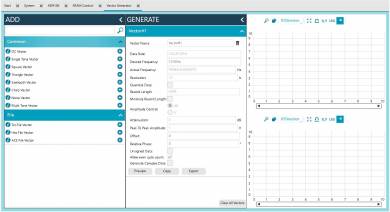
ACE includes a vector generation tool accessible from the left side menu.
Loading SRAM Vector
Figure 8a. AD9106 SRAM Control | Figure 8b. AD9102 SRAM Control
From the SRAM Control Tab, select the vector file path in the Vector file text box.
Click
Write SRAM Data to write the data in the AD910x
SRAM Addresses.
To read
SRAM data, click the
Read SRAM Data.
SRAM registers are left justified. Data written to memory map are automatically shifted to the left by
4 bits for AD9106 and
2 bits for AD9102.
Using the Vector Generator
The plugin also includes a vector generation tool also accessible in the SRAM Control Tab

Figure 9a. AD9106 Vector Generator | Figure 9b. AD9102 Vector Generator
To Generate a Vector
From the
SRAM Control tab, Click
Generate Vector button. This will prompt user to VectorGenerator Tab.
From ADD wizard, choose from the available common vectors then click (+).
From GENERATE wizard, set the desired vector characteristics.
Click Preview to generate a preview of the waveform.
Click Export. This will generate a text file.
Save file to a known folder.
Ensure that vector characteristics is similar to Figure 17 or that:
Data Rate is similar to DAC Clock.
Record length is 4096.
Resolution is 12 bits for AD9106 and 14 bits for AD9102.
Amplitude control should be in
dB.
To Preview a Vector file
From ADD Wizard under File, select Txt file vector. This will add a vector to GENERATE wizard.
From GENERATE wizard, Select Real Vector and correct file path for your vector file.
Select correct resolution used and Data Rate.
Click Preview.
There are sample vector text file in the default Vector File Path that can be used as reference.


