


This version (15 Feb 2022 02:28) was approved by Melissa Lorenz Lacanlale.The Previously approved version (28 Sep 2021 07:26) is available.
Table of Contents
EVALUATING THE AD9739 RF DIGITAL-TO-ANALOG CONVERTER
Preface
This user guide describes both the hardware and software setup needed to acquire data capture from AD9739-R2-EBZ evaluation board to characterize AD9739 14-Bit, 2.5 GSPS, RF Digital-to-Analog Converter.
This guide shows how AD9739-R2-EBZ works with SDP-H1 or ADS7-V2 controller board developed by Analog Devices. Link to the previous user guide document is provided for customers who still have the DPG3 controller board.
Typical Setup

Figure 1a. EVAL-AD9739 Setup with SDP-H1

Figure 1b. EVAL-AD9739 Setup with ADS7-V2
Tip: Click on any picture in this guide to open an enlarged version.
Helpful Files:
- Download the Quick start Guide and AD9739 Updatefor DPG3 users
- Data Sheet: AD9739 Data Sheet
- IBIS Model: IBIS Model
- Bill of Materials: ad9739-cmts-ebz_reva, ad9739-cmts-ebz_revb, ad9739-ebz_reva, ad9739-mix-ebz_reva,ad9739-r2-ebz_revab
Software Needed:
- DPG Lite (Recommended; Installed with ACE) or DPG Downloader
Known Issue: ACE may fail to detect HS-DAC boards, details here.
Hardware Needed:
- AD9739-R2-EBZ Evaluation Board
- SDP-H1 (EVAL-SDP-CH1Z) or ADS7-V2EBZ
- AD-DAC-FMC-ADP High-Speed DAC Evaluation Board to FMC Adaptor Board
- 5Vdc 2A Power Supply
- PC with ACE and DPG Lite Software Applications
- High-Frequency Continuous Wave Generator
- Signal/Spectrum Analyzer
- USB-A to USB-Mini Cable
- (2) SMA Cables
- Power Supply to SMA cable
- The following are included in SDP-H1 Evaluation Kit:
- 12Vdc 2.5A Wall Wart
- USB-A to USB-Mini Cable
- The following are included in ADS7-V2 Evaluation Kit:
- 12V 60W AC/DC Power Supply
- Power Cord
- USB-A to USB-B Cable
Quick Start Guide
- Attach the evaluation board to the FMC connector of SDP-H1 or ADS7-V2 using the AD-DAC-FMC-ADP adapter board. Connect continuous wave generator for clock input to J3, and the DAC output from J1 to a signal/spectrum analyzer. Connect the evaluation board to PC via USB, a 5Vdc 2A power supply to J17. Refer to Figures 1a and 1b.
- If using SDP-H1, set clock input to 300 MHz and 0 dBm. Connect SDP-H1 to PC via USB and to a 12Vdc wall wart.
- If using ADS7-V2, set the clock input to 2 GHz and 0 dBm. Connect ADS-V2 to PC via USB and to a 12V 60W AC/DC power supply. Switch the board ON using S1 beside the connector for 12V supply.
- Open ACE. The board will automatically be recognized by the software. Otherwise, install the plugin for AD9739 evaluation board. From the AD9739-EBZ tab, Click “Run Example Startup Routine (Sync Disabled)”.
- If using SDP-H1, The MU Controller Locked indicator should light up as shown in figure 2a.
- If using ADS7-V2, The first three indicators should light up as shown in figure 2b.
 Figure 2a. ACE Initial Board Configuration Wizard for SDP-H1
 Figure 2a. ACE Initial Board Configuration Wizard for ADS7-V2
- Double click the AD9739 Box to open chip view.
- If using SDP-H1, The DLL_LOCKED indicator should light up as shown in figure 3a.
- If using ADS7-V2, All three indicators should light up as shown in figure 3b.
 Figure 3a. ACE Initial Board Configuration Wizard for SDP-H1
 Figure 3b. ACE Initial Board Configuration Wizard for ADS7-V2
- Start DPG Lite or DPG Downloader.
- At the SDP-H1 settings, ensure that Evaluation board is equal to AD9739 and DCO frequency of around 75 MHz should be displayed.
- At the ADS7-V2 settings, ensure that Evaluation board is equal to AD9739 and DCO frequency of around 500 MHz should be displayed.
- In DPG Lite or DPG Downloader, from the Add Generator Waveforms pulldown menu, select Single Tone and apply the settings as shown in Figures 4a and 4b.
- When using SDP-H1, set Data Rate to 300 MHz and Desired Frequency to 20 MHz.
- When using ADS-V2, set Data Rate to 2 GHz and Desired Frequency to 180 MHz.
- Continuing on setting up DPG Lite or DPG Downloader, set DAC resolution to 14 bits. Check off the Unsigned Data box.
- Select the Single Tone from the Data Vector pulldown menu
 Figure 4a. DPG Lite session for SDP-H1
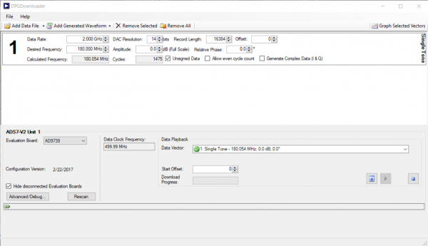 Figure 4b. DPG Lite session for ADS7-V2
- Press the download arrow and then the play button. The FFT plots similar to Figures 5a and 5b should appear in the signal/spectrum analyzer.
 Figure 5a. EVAL-AD9739 FFT for Data Rate = 300 MHz, Fout = 20 MHz using SDP-H1
 Figure 5b. EVAL-AD9739 FFT for Data Rate = 2 GHz, Fout = 180 MHz using AD7-V2
Troubleshooting
This section lists items to check and practices to use when debugging any unexpected performance of a board. If unexpected results occur:
- Check if the Voltage supply test points of the evaluation board has the correct value.
- Check if all (3) blue LEDs on the AD-DAC-FMC-ADP board is lit up. Reconnect the board to the FMC connector of SDP-H1 if not lit up.
- Check if the SDP-H1 is being supplied properly by 12Vdc adaptor. Some LEDs on the SDP-H1 should lit up.
- Power cycle both the SDP-H1/ADS7-V2 and the AD9739 evaluation board.
- Check on the Spectrum Analyzer if the DAC clock inputs are properly driven. For 300MHz clock using SDP-H1, the spectrum analyzer should detect a weak signal at 300MHz. For 2GHz clock using ADS7-V2, the spectrum analyzer should detect a weak signal at 2GHz. If not detected, check properly the clock source and connections.
- Disconnect and reconnect the SDP-H1 /ADS7-V2 and AD9739 evaluation board. Reopen DPG Lite software.
resources/eval/dpg/ad9739-ebz.txt · Last modified: 15 Feb 2022 02:28 by Melissa Lorenz Lacanlale