


This version is outdated by a newer approved version. This version (26 Feb 2015 22:12) is a draft.
Approvals: 0/1
This version (26 Feb 2015 22:12) is a draft.Approvals: 0/1
This is an old revision of the document!
Table of Contents
AD9154-M6720-EBZ Evaluation Board Quick Start Guide
Getting Started with the AD9154-M6720-EBZ Evaluation Board and Software
What's in the Box
- AD9154-M6720-EBZ Evaluation Board for DPG3
- Evaluation Board CD
- Mini-USB Cable
Recommended Equipment List
- +5VDC Lab Power Supply
- Two Sinusoidal Clock Sources
- Spectrum Analyzer
- Oscilloscope
- Data Pattern Generator Series 3 (DPG3)
Introduction
The AD9154-M6720-EBZ connects to a DPG3. The AD9154 is a quad JESD204B signal processing RF Digital to Analog Converter. The DPG3 automatically formats the data and sends it to the AD9154-M6720-EBZ via its JESD204B lanes. The AD9154-M6720-EBZ includes an AD9154 and two ADRF6720-27 Wideband Quadrature Modulators with Integrated PLL and VCO. There is a board level passive low pass filter between the output of each AD9154 DAC and its corresponding ADRF6720-27 baseband input. The Evaluation Board (EVB) runs from a single +5V lab supply. A clock distribution chip AD9516 is included on this EVB as a clock fan-out and frequency divider for the DACCLK, JESD204B SYSREF signals, and a CFRAME clock used by the DPG3.
AD9154 and ADRF6720-27 Evaluation Software
The AD9154 and ADRF6720-27 Evaluation software runs on the easy-to-use SPIPro graphical user interface (GUI). It is included on the Evaluation Board CD.
Hardware Setup
Connect +5.0V to P5, GND to P6. A low phase noise high frequency clock source should be connected to the SMA connector J1 (CLK_IN). A spectrum analyzer should be connected to the SMA connector J4, RF_OUT_1. Connect a low phase sinusoidal signal source to J18, the RF local oscillator input to ADRF6720-27_1. (The ADRF6720-27 on-chip LO synthesizer is not used in this quick start guide.) The evaluation board connects to the DPG3 through the connector P4. The PC is connected to the EVB using the mini-USB connector XP2. Figure 1 shows a block diagram of the set-up.

| Figure 1. AD9154-M6720-EBZ Lab Block Diagram |
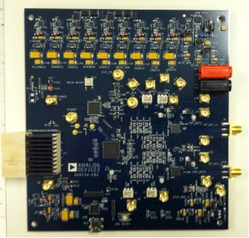
| Figure 2. Top view of AD9154-M6720-EBZ |
Getting Started
The PC software is included in the CD shipped with the EVB. The installation includes the DPG Downloader software as well as all the necessary AD9154 files including schematic, board layout, datasheet, and other files.
Initial Set-Up
1. Install the DPG Downloader and SPIPro software and support files on your PC. Follow the instructions in the installation wizard and use the default (recommended) installation settings.
2. Use a USB cable to connect the EVB to your PC and connect the lab equipment to the EVB.
3. Connect the DPG3 unit to your PC and turn on the unit.
Single Tone Demonstration
These settings configure the AD9154 to output a 182Mhz -1dbFS sine wave using the DPG3 on all four AD9154 DACs. The DAC output signals are I/Q pairs. An external LO of 1.36GHz is supplied to the ADRF6720-27 chips. The AD9720-27 chips perform a complex single sideband up-conversion of the sine wave I/Q pairs to a 1542MHz RF signal at the RF_OUT_1 and RF_OUT_2 connectors J4 and J14. 1. Configure the hardware according to the hardware set-up instructions given in the Hardware Setup section above. Set the frequency of the DAC clock signal generator to 1500MHz, and the output level to 3dBm. Set the frequency of the ADRF6720-27 Synthesizer Local Oscillator Source to 1.36GHz and set its output amplitude to +4dbm. The spectrum analyzer can be configured as shown in Figure 7 with a resolution bandwidth of 100kHz. Choose an Input Attenuation of 24dB. 2. On your lab computer, open the AD9154 SPIPro application (Start > All Programs > Analog Devices > AD9154 > AD9154 SPI). You will see the GUI shown in Figure 7 come up.
<WRAP center>

| Figure 3. AD9154 SPIPro at start up |
</WRAP center>
<WRAP center>
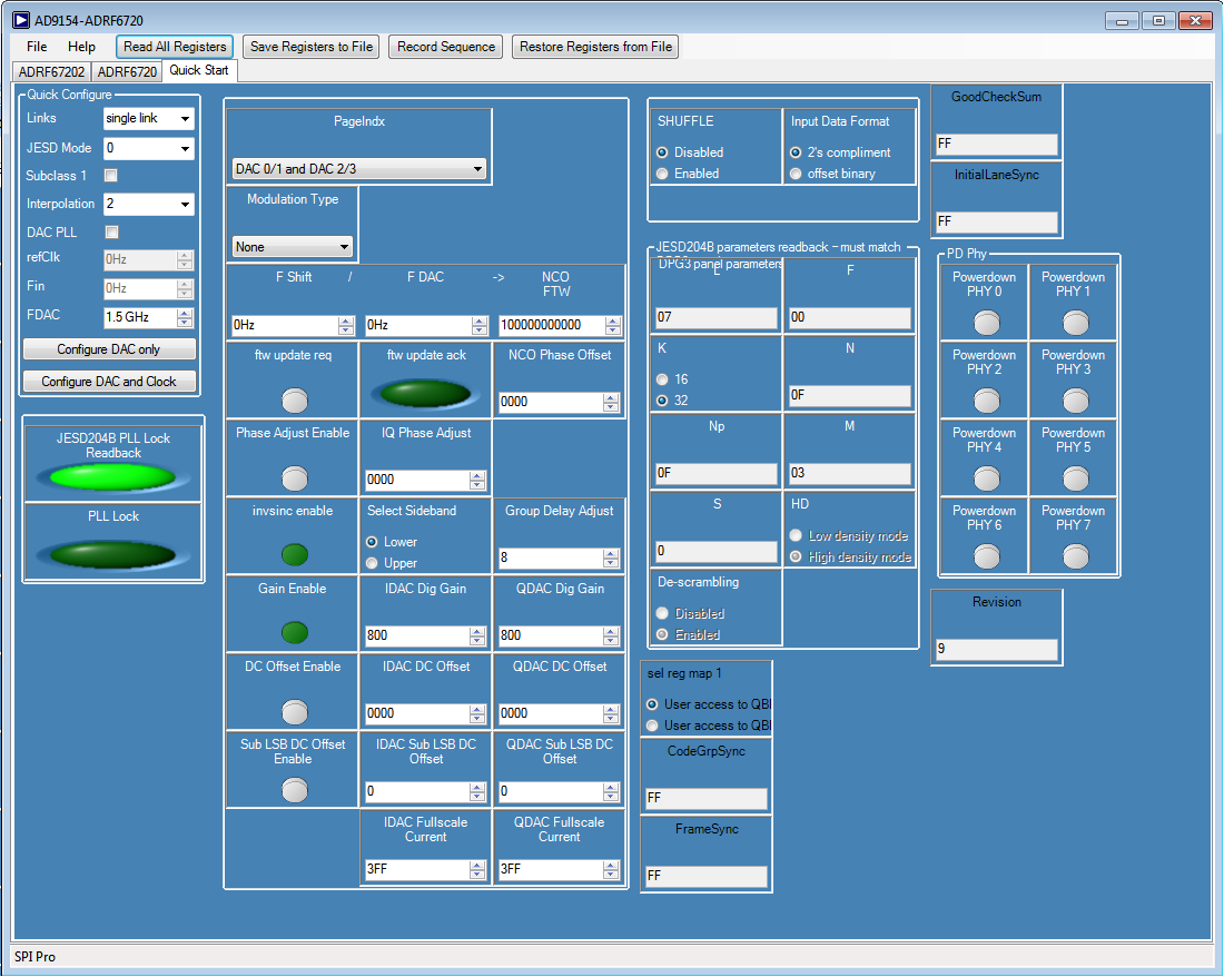
| Figure 4. Fully Configured AD9154 SPIPro |
</WRAP center> 3. SPIPro Start Up Sequence.
a. In the Quick Start Tab Select “Single” for Links.
b. Select JESD Mode 0. c. Uncheck the “Subclass 1” box
d. Select “2” for Interpolation.
e. Press the “Configure DAC and Clock” Button
f. The JESD204B PLL Lock Readback light should turn green and register bit settings will be populated. The GUI will look like Figure 4, except that values in “CodeGrpSync”, “FrameSync”, “GoodCheckSum”, and “InitialLaneSync” may be different because the link JESD204B Transmitter has not yet been set up.
g. Load Register Settings into the ADRF6720 devices by clicking “Restore Registers from File” and locating “ADRF6720.csv”. This should be located at the install directory for the AD9154 SPIPro application.
h. Click on “ADRF6720” tab for Mod 1 and confirm the GUI matches Figure 5 below.
<WRAP center>

| Figure 5. Configured SPIPro ADRF6720 tab of the AD9154 SPI software |
</WRAP center>
i. Click on “ADRF67202” tab for Mod 2 and confirm the GUI matches Figure 6 below.

| Figure 6. Configured SPIPro ADRF67202 tab of the AD9154 SPI software |
4. DPG Downloader Start Up Sequence
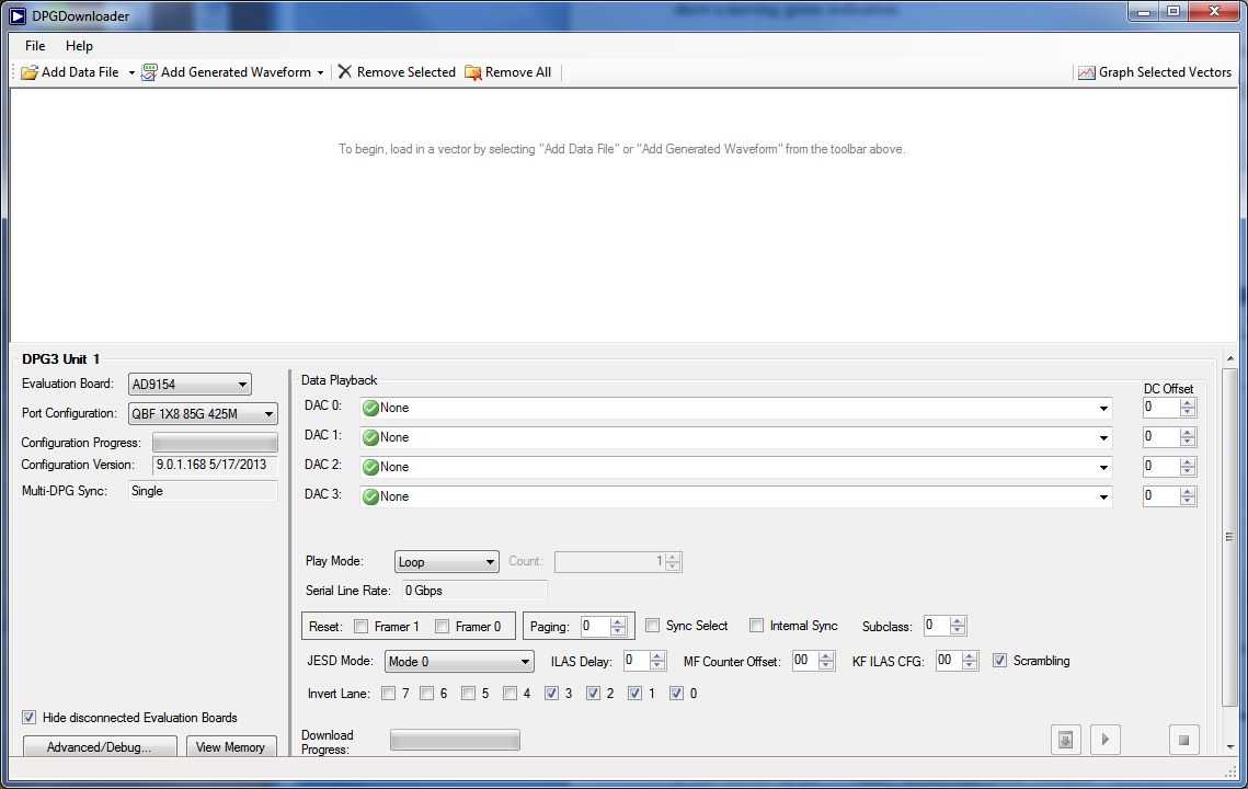
a. Open DPG Downloader. (Start > All Programs > Analog Devices > DPG > DPGDownloader). DPG Downlader GUI will come up as shown Figure 7.
b. Select the Port configuration QBF 1×8 85G 425M. The configuration progress bar will then show a moving green indication.
c. Once port configuration is complete, select “add generated waveform” and “single tone”.
d. Set Data Rate to 750Mhz, Desired Frequency to 182Mhz, Amplitude to -1.0 dBFS, uncheck unsigned, check Generate Complex Data (I&Q).
e. Under Data Playback, select I data for DAC 0 and DAC2, and Q data for DAC 1 and DAC3.
f. Click Download Button and the Play Button. The spectrum in Figure 9 will appear on J4, RF_OUT_1. The Serial Line Rate will be 7.5Gbps.
| Figure 7. DPG Downloader Panel at start up |
</WRAP center>
<WRAP>
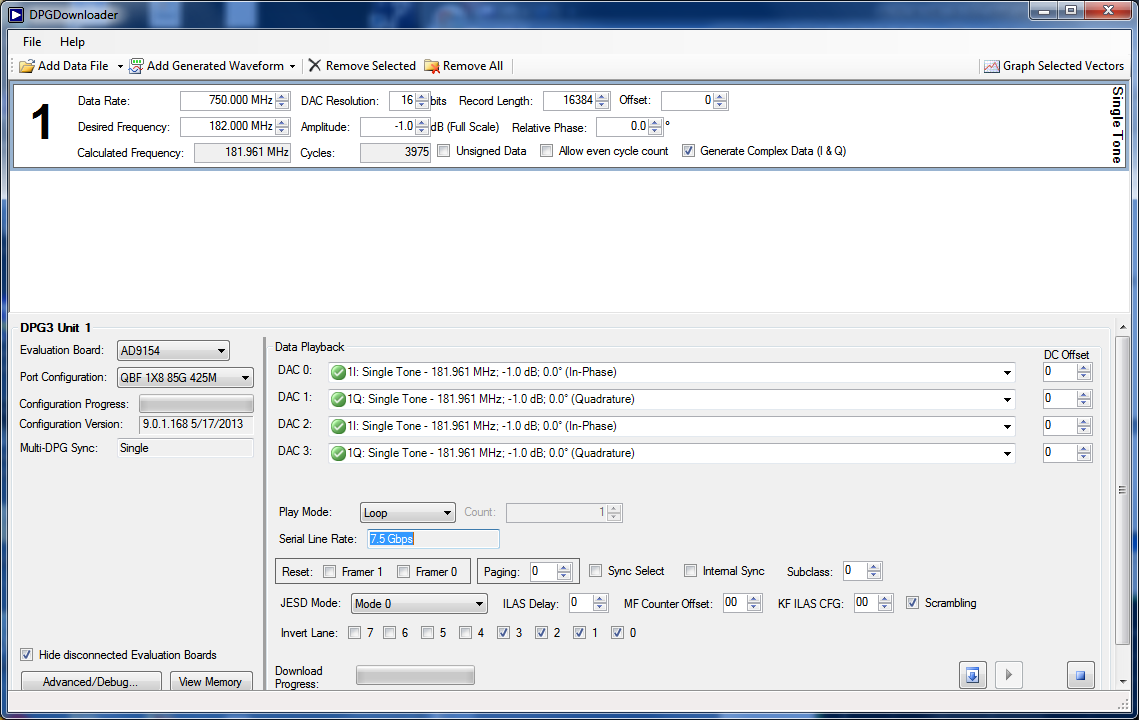
| Figure 8. Configured DPG Downloader Panel |
</WRAP >
5. On SPIPro Quick Start Tab, click “Read All Registers” and confirm the GUI looks the same as Figure 4.
6. The current on the 5V supply should read about 2300mA – 2400mA.

| Figure 9. ADRF6720-27 RF Output Spectrum Analyzer Display |
</WRAP >
resources/eval/dpg/ad9154-m6720-ebz.1424985150.txt.gz · Last modified: 26 Feb 2015 22:12 by Larry Welch