


This version is outdated by a newer approved version. This version (29 Apr 2015 20:31) is a draft.
Approvals: 0/1
This version (29 Apr 2015 20:31) is a draft.Approvals: 0/1
This is an old revision of the document!
Table of Contents
AD9578 Evaluation Board User Guide
Evaluation Board Features
- Simple power connection using 6 V wall adapter and on-board voltage regulators
- Prepopulated 49.152MHz XTAL to synthesize any frequency 11.8MHz – 919MHz
- 2 reference input SMA connectors
- 10 ac-coupled differential SMA output connectors (5 differential paths)
- USB connection to PC
- Microsoft Windows-based evaluation software with simple graphical user interface
- Supports 32-bit and 64-bit versions
- SPI and eFuse programmable
- Two 12 pin headers to interface with Avnet LX9 MicroBoard
Equipment Needed
- Reference oscillator or signal generator (Optional)
- Other evaluation board to be clocked or test equipment
- Oscilloscope, spectrum analyzer, phase noise analyzer
- SMA cables (50 Ω)
- 6 V wall supply (provided)
- USB cable (provided)
Online Resources
General Description
The AD9578 evaluation board is a compact, easy-to-use platform for evaluating all features of the AD9578. The AD9578 is a programmable synthesizer intended for jitter attenuation and asynchronous clocking applications in high performance telecommunications, networking, data storage, SERDES and PHY applications. The evaluation board consists of one prepopulated 49.152MHz crystal and optional single ended SMA inputs to drive the XO2 and XO4 pins. Each output is accessed through edge launch ac-coupled SMA connectors. The on board power supply allows users to simply operate the AD9578 with 2.5V or 3.3V voltages by altering a few jumper settings. Use this user guide in conjunction with the AD9578 data sheet and software documentation available at www.analog.com.

Figure 1. AD9578/PCBZ
Evaluation Board Hardware
The following instructions are for setting up the physical connections to the AD9578/PCBZ evaluation board.
Power Connections
The AD9578/PCBZ is setup by default to power the AD9578 and remaining circuitry with 3.3V using the provided 6V wall power supply. The evaluation board can be configured to operate at 2.5V when using the 6V wall supply by removing jumpers P507 and P509.
Connecting External Supplies
An external power source may be connected to both the AD9578 and digital circuitry by using header P506. The AD9578 and digital circuitry must operate at the same voltage level for proper functionality. To connect an external supply:
- Remove jumpers P502 and P510 and disconnect the 6V wall supply.
- Connect either 2.5V or 3.3V to pins 1,2,5,6 of the P506 header. Pins 3 and 4 are a shared universal ground for both power planes.
PC Connections
The following instructions assume the evaluation board is set up with the default power configuration as described in the Power Connections section.
- Download the latest AD9578 evaluation software from analog.com website.
- Install the AD9578 evaluation software; uninstall prior versions of the software before installation updates. Administrative privileges are needed to install the software.
- Connect the 6V wall power supply to the main power connector labeled P500.
- Connect the USB cables to the evaluation board and the computer. The red LED labeled CR300 on the evaluation board should illuminate.
- If the Found New Hardware Wizard window automatically appears when the evaluation board is connected, select Install the software automatically and click Next.
- The Found New Hardware Wizard window may appear twice, and a system restart may be required.
Refer to the Evaluation Board Software section for details on running the AD9578 evaluation board software.
Signal Connections
XO Inputs
The AD9578 evaluation board comes prepopulated with a 49.152MHz crystal (Y101) across the XO1 and XO2 pins. Crystal Y102 connects to the XO3 and XO4 pins and is not prepopulated. Any crystal between 22MHz and 54MHz in a 3.2mm x 2.5mm package is suitable but care must be taken to select the proper load capacitance to ensure oscillation.
Expand XO as REFIN
Outputs
The REFOUT output (J217 and J218) can be configured to be a copy of either XO input or a divided version of the applied REFCLK input (includes divide by 1). The frequency source of OUT1 and OUT2 is PLL1 and the source of OUT3 and OUT4 is PLL2. The logic level of each output is selectable between CMOS, HCSL, LVDS and LVPECL. All outputs are terminated as LVPECL by default and ac coupled to their respective SMA connectors. Using any logic type other than LVPECL will require modifications to the terminations. Refer to the AD9578 datasheet for the recommended termination for each logic type.
SPI Bus
The AD9574/PCBZ default configuration allows a PC running the AD9578 evaluation software to read and write the various registers of the AD9578 via a USB connection. The user may interface with the SPI bus from an external SPI controller by removing jumpers P108-P110 and driving the appropriate signals to the SDO, SCK, CSB, and SDI nodes.
Default Evaluation Boards Setup Summary
- Jumper P508 set to SW_OUT to provide the switcher output voltage to on board LDO regulators.
- Jumpers P507 and P509 are populated to set LDO regulator outputs to 3.3V.
- Jumpers P502 and P510 are populated to connect LDO voltages to AD9578 and microcontroller.
- 49.152MHz crystal oscillator connected to the XO1 and XO2 inputs is populated.
- OUT1 (J209 and J210), OUT2 (J211 and J212), OUT3 (J213 and J214), OUT4 (J215 and J216), and REFOUT (J217 and J218) are terminated for LVPECL and ac coupled.
Evaluation Board Software
Use the following instructions to set up the AD9578 evaluation board software.
Use the following instructions to set up the AD9578 evaluation board software.
Software Installation
Do not connect the evaluation board until the software installation is complete.
- The latest evaluation software and documentation can be downloaded from the AD9578 evaluation board page..
- Once downloaded, double-click AD9578 Evaluation Software Setup.msi. (Note that the website may have a newer version.) Follow the installation instructions.
Running the Software
Power up and connect the evaluation board to the PC. See the Evaluation Board Hardware section for details on the various connectors on the evaluation board. At start up, the AD9578 evaluation software checks to see if an evaluation board is connected. If no board is connected, the message in Figure 2 will appear.
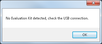
Figure 2. Evaluation Board Not Connected Message
Clicking OK allows the software to be used without a connected evaluation board. This mode is convenient for creating register setup files when an evaluation board is not present. If an evaluation board is present and the error message appears, check power and USB connections and re start the program. When and evaluation board is connected before starting program, the standard GUI appears as shown in Figure 6. It is possible to connect the evaluation board after the software is started by selecting File/Select Hardware after the board has been powered and USB cable connected. When a board is properly connected, Read All Successful will appear in the Comments box.
Setup Files
The AD9578 software allows the user to save a setup file containing all of the current register settings generated by the software, which can be later read, and re used.
To create a setup file:
- Open the AD9578 software with or without an evaluation board present.
- Adjust the AD9578 settings within the GUI.
- Select File/Save All Registers and enter a file name and file path where the register settings to be saved.
To load a setup file:
- Select File/Load All Registers. The setup file will automatically be loaded into the evaluation board active settings and displayed in the Main Window.
Quick Start Guide
Once the evaluation software is loaded and the evaluation board is connected, use the following steps to lock both PLLs on the AD9578. These steps use the on board 49.152MHz crystal as a reference for both PLL1 and PLL2 and the default power configuration using the provided 6V wall supply as described in the Evaluation Board Hardware section. The quick start guide covers only simple PLL operation. See the AD9578 datasheet and Evaluation Software Components section for a detailed explanation of the various AD9578 features. The following case is an example of the AD9578 using the values in Table 1.
Table 1. Quick Start Summary
| Parameter | Value |
|---|---|
| Input Frequency | 49.152MHz across XO1 and XO2 |
| PLL1 Reference Selection | Crystal 1 |
| PLL2 Reference Selection | Crystal 1 |
| OUT1 Frequency and Logic Type | 125MHz LVPECL |
| OUT2 Frequency and Logic Type | 156.25MHz LVPECL |
| OUT3 Frequency and Logic Type | Disabled |
| OUT4 Frequency and Logic Type | 155.52MHz LVPECL |
| REFOUT Frequency and Logic Type | Disabled |
- Type the Crystal 1 reference frequency in the text box located in the upper left of the Main Window.
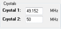 Figure 3. Crystal 1 Frequency Text Box
- Select Crystal 1 as the PLL1 Reference and PLL2 Reference to using the drop down in the upper right of the Main Window.
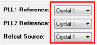 Figure 4. Input Reference Selection
- Select the appropriate logic level for Output 1 through Output 4 and REFOUT by using each logic level drop down as shown in Figure 5 and type the desired frequency in each Output1 through Output 4 text box.
 Figure 5. Logic Level Selection and Frequency Input
- Press the Autocalculate button at the bottom of the screen. The software will calculate to the closest possible output frequency given the specified reference frequency.
- Press the Configure button. This will load all of your settings into the AD9578. Pressing Read should turn the PLL1 and PLL2 lock indicators blue signifying that both PLLs are locked. All four outputs will be toggling at the desired frequencies.


Evaluation Software Components
Main Window
 Figure 6. AD9578 Evaluation Software Main Window
Active and Inactive Controls
Upon startup, many controls in the AD9578 main window are inactive and grayed out. To manipulate all controls within the main window check the Advanced box in the lower right corner of the main window.
 Figure 7. Advanced Box
Checking the Advanced box expands the main window to include a full register map and many other features, which are explained in the following sections of the user guide.
Invalid Value Indication
Certain combinations of values can cause the AD9578 operating parameters to exceed the valid ranges specified in the datasheet. In these cases, the invalid entry will be highlighted in yellow and a message will appear in the Comments box explaining why the entry is invalid.
The following conditions are checked within the software:
- Crystal 1, Crystal 2, and External Reference input frequency ranges
- Output 1 through Output 4 and Reference Output frequency ranges.
- All text box entries within the expanded Main Window when the Advanced box is checked.
Autocalculate, Configure, and Read Buttons
The Autocalculate button takes the user defined reference input and output frequency parameters and automatically configures the proper PLL settings using the Frequency Wizard. Autocalculate is disabled in Advanced Controls mode. For more information on the Frequency Wizard and Advanced Controls, refer to the respective sections in this document.
The Configure button loads all of the parameters from the GUI into the AD9578 on the evaluation board. “Write All Successful” will appear in the comments box upon the completion of a successful write operation.
The Read button reads the current register values from inside the AD9578 and loads them into the Main Window. “Read All Successful” will appear in the comments box upon the completion of a successful read operation.
Input Frequency Section
The input frequency section of the Main Window is used to identify the reference input frequency of either crystal input. Each text box (Crystal 1 and Crystal 2) is editable by the user and is used to calculate the output frequency of each output. If a differential input is used for an external reference, check the Differential Input check box.
PLL Input Reference Selection
The reference input to each PLL is specified by using the various drop down menus shown in Figure 8.
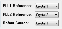 Figure 8. PLL Input Reference Selection Drop Downs
Each PLL and REFOUT reference frequency can be supplied by Crystal 1, Crystal 2, or an external reference input Ref In. Crystal 2 and Ref In cannot be used simultaneously. The selection of Ref In or Crystal 2 is controlled by using the Ref In/Crystal 2 drop down.
PLL1 and PLL2 Default Controls
The AD9578 evaluation software automatically configures the settings for each PLL based on user inputs for both the reference frequency and output frequency by using an internal frequency wizard and the Autocalculate button. To enable an output text box, change the appropriate logic level in each outputs allocated drop down menu. Logic levels are selectable from LVDS, LVPECL, HCSL, and LVCMOS. Once a text box is enabled, the user may enter the desired output frequency. Pressing Autocalculate will then calculate the value closest to the user input. Figure 9 shows a standard configuration in the software’s default mode using Output 1 and Output 3.
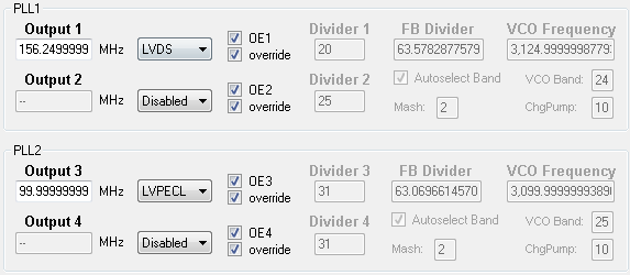 Figure 9. PLL1 and PLL2 Default Controls
The OEx and override check boxes allow the user to manipulate the various output enable bits from the register 0x02 of the AD9578. Default operation is for both boxes to be checked, allowing the software to have control over each output.
PLL1 and PLL2 Advanced Controls
Clicking the Advanced check box, as shown in Figure 7, expands the Main Window to allow the user to interact with individual PLL settings and the entire register map as the part is currently configured.
 Figure 10. PLL1 and PLL2 Advanced Controls
In Advanced Controls mode, all PLL feedback dividers, output dividers, charge pump and VCO settings are editable by typing in the various text boxes. It is recommended to allow the software to auto select the VCO band being used when in Advanced Controls mode. In this mode, all of the output frequencies are calculated based off the user’s settings for the reference frequencies and feedback/output division settings. The Autocalcuate feature is thus disabled in Advanced Controls mode. Another feature in Advanced Controls mode is the Reset Fuses Button. This button allows the user to reset the AD9578 to its default fuse blown settings without power cycling evaluation board. The default fuse blown settings are then displayed in the Main Window.
Figure 11. Reset Fuses Button
resources/eval/ad9578-user-guide.1430332276.txt.gz · Last modified: 29 Apr 2015 20:31 by Kyle Slightom