


This version is outdated by a newer approved version. This version (09 Aug 2018 02:02) is a draft.
Approvals: 0/1
This version (09 Aug 2018 02:02) is a draft.Approvals: 0/1
This is an old revision of the document!
Table of Contents
ADXRS450 Gyro Board for FIRST Robotics
The ADXRS450 gyro board is a single-axis industrial sensor, designed to get teams up and running quickly without having to load 3rd-party libraries. This gyro is readily accessible through multiple sources and is recommended for all teams, including those with no gyro experience. It plugs directly into the SPI port on the RoboRIO and libraries are already included in WPILib - all you have to do is declare it in your robot code and use it!
Supporting code for the ADXRS450 only exists in the three main programming languages supported by FIRST. If your team wants to use this board with other programming languages, please refer to the ADXRS450 product datasheet for more information on how to communicate with this gyro via SPI.
Getting Started
There are currently two versions of the FRC Gyro board. The libraries detailed on this page apply to both of these versions, however there are some considerations to take into account for each one.

FRC Accelerometer & Gyroscope (REV1)
This version was made available to FRC teams through 2016. It includes both the ADXRS450 and the ADXL362 accelerometer. This board continues to be supported by WPILib and you can even use the WPI Accelerometer library to connect to it if you want. Just note that the accelerometer component is no longer supported, so there's a chance that new RoboRIO firmware released each year may not work with this sensor.

FRC Gyro with Chip Select Jumper (REV2)
This version of the gyro board was available for the 2017 and 2018 seasons. The accelerometer was removed in favor of a jumper that allows you to configure the “chip select” pin used to communicate with the sensor in case you want to have other devices on the same SPI bus. To use the libraries built-in to WPILib, the default configuration should be to connect the jumper between the CS0 pin and the unlabeled center pin. If you want to use a different setting, you will need to change the “chip select” pin address when initializing the sensor in your robot code. The sections below detail how to do this for each of the three supported languages.
FRC Gyro With Solderable Jumpers (REV3)
This is the lower-cost, more reliable version of the sensor board made available to teams starting with the 2019 season. To make using the sensor even easier for teams, we removed the chip select pin jumpers and added a solderable jumper. This change improves reliability as there is no risk of the jumper accidentally getting lost or removed, but still allows teams the flexibility of adding additional sensors to the SPI bus.
A Note on Gyro Calibration
To help the robot identify a starting angle position more accurately and remove most gyro drift, it is recommended that you allow the robot to calibrate the sensor first. It will do this by taking several readings from the sensor and average them together to obtain your “zero” angle. Calibration typically takes about 30 seconds.
Remember, the ADXRS450 is a rate sensor, not a raw angle sensor, so any movement during this calibration routine will cause the robot to think that movement is part of the natural drift that the sensor has. Because of this, it is imperative that the robot is left completely stationary during this calibration period.
Calibration should be performed as soon as the robot is powered on, to prevent the calibration routine from interfering with any autonomous code execution. You can usually tell that your robot was bumped during calibration if you notice that your gyro angle readings are drifting off into space very rapidly. In LabVIEW, this calibration is done as part of the initialization. But in C++ and Java, you must explicitly call the calibrate routine. You can read more info on your team's specific language below.
Using the Gyro in LabVIEW
If you need some help getting up and running in LabVIEW, check out the WPI Screensteps page to get started on the basics.
As with any LabVIEW robot project, there are a few places you must place code in order to use the gyro board: Begin.vi, Finish.vi, and any .vi in which you want to access gyro data. The screenshots in this example assume you are starting from the Arcade robot project, but the steps are the same for any robot project.
Setting Up the Gyro in Begin.vi
Open your robot project, or create a new one if you don't have one created already, and open up your Begin.vi block diagram. This can be found in the project window under Team Code.
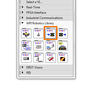
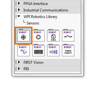
The first step is to create a new instance of the gyro, then assign a reference name to it so that you can call the gyro reference anywhere in your robot code. You can find the gyro VI under WPI Robotics Library --> Sensors --> Gyro. Bring the Gyro Open VI into your Begin.vi code. It doesn't matter where you place it in this VI.

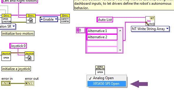
When you first bring the instance into your code, it will default to an analog gyro, so you will need to change the type using the drop-down menu below the VI's icon. Select “XRS450 SPI Open” to tell your robot that you're working with the ADXRS450 board.
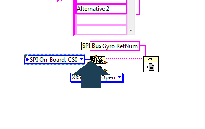
Next, you need to tell LabVIEW which SPI “chip select” (CS) it will be using. Right click on the “SPI Bus” pin on the Open VI and click “Create --> Constant” to insert an enumerated variable. LabVIEW will automatically assign the gyro to CS0, which is the default. Unless you are using the CS Jumper version of the gyro and want to use C1 or C2 by moving the jumper, do not change this variable!
Now you need to assign a reference name to this gyro so that you can refer to it in other VIs. Grab the Registry Set VI from the Gyro palette and place to the right of your Open VI. Then, connect the GyroDevRef pin on the Open VI to the GyroDevRef on the Registry Set VI.


Now you need to assign a name to your gyro. Right click on the “refnum name” pin on the Registry Set VI and click “Create --> Constant” and create a unique name that you will use to refer to this gyro in the rest of your code. I've left the default value of “My Gyro RefNum” but you can change this to whatever you want.


Closing Communication in Finish.vi
Whenever you open a communication bus in your robot code, you have to close those communications when your robot code finishes, just like you have to close all of the programs running on a computer before you can shut it down properly. This is done in the Finish.vi code. Open your robot project and open up the Finish.vi block diagram. Then, place an instance of the Registry Get VI on the outside of the Flat Sequence Structure (the film strip boxes), and an instance of Gyro Close VI on the inside of the first panel of the Flat Sequence Structure.

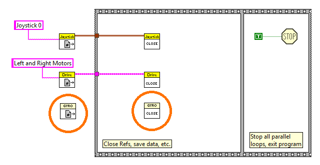
Then, connect the GyroDevRef pins of both VIs together.

Now, create a string constant by right clicking on the Gyro RefName pin on the Registry Get VI and clicking Create --> Constant. Rename this string to be the same name you used when instantiating the gyro in your Begin.vi code. I've left mine as the default, since that's what I used in my Begin.vi code. You're now ready to call data from the gyro!

Using the Gyro in Your Robot Code
 There are several use-cases for using the gyro output in your code. You may want to use the gyro output to accurately track your robot's direction of travel so that you drive straight, or rotate to the right angle. This offers you more precision than simply telling the motors to drive together at the same rate to move forward. For this kind of action, you will use the Get Angle VI.
 You may also want to be able to reset the gyro, since any gyro will have some drift as the match progresses. Think of it like zeroing a weight scale - it's good practice to “tare” or “zero” the scale when you first turn the scale on, or when you want to use a cup or container for whatever you're measuring. For this, you would use the Reset Gyro VI.
In my example below, I'm going to be reporting the gyro angle to the driver station from the Teleop.vi. In practice, you should really put this type of action in the PeriodicTasks.vi, but this is just an example. These steps will apply to anywhere you want to use either of the VIs listed above.
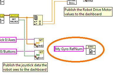
To use any Gyro VI, you first have to call the Gyro you initialized in Begin.VI. You saw this when we completed our gyro setup in Finish.vi. Go ahead and place an instance of Gyro Registry Get in your block diagram and create the constant for your gyro name. Don't forget to change the constant value to whatever you called your gyro in Begin.vi! I've left mine as the default, since that is what I used.
Now, place an instance of the Get Angle VI next to it, and wire it up as shown below, just like you did for Gyro Close in your Finish.vi block diagram. Then, go to your Dashboard pallet in the WPI Robotics Library and grab the NT Write Value VI and place it next to your Get Angle VI. Note that when you first place this VI in your code, it will show as expecting a Boolean. This VI can actually automatically detect which data type you are feeding it and adjust accordingly. You can also use the drop-down menu below the VI icon and explicitly specify what data type you want it to expect, but it is usually best to leave it set to Automatic as shown below.
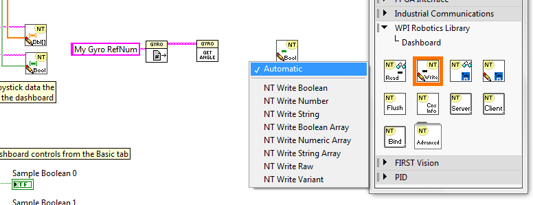
Now, connect the Angle pin on the Get Angle VI to the Boolean pin on the driver station VI you just placed. You will see that the icon will change to indicate what kind of data you are sending, which in this case is a Double. Right click on the Name pin and select Create --> Constant and write a name for the indicator that will appear on the Driver Station.

first/adxrs450_gyro_board_frc.1533772928.txt.gz · Last modified: 09 Aug 2018 02:02 by Kristen Chong